Business Process Model Notation diagrams - BPMN 2.0
Business Process Model and Notation (BPMN) is a standardised diagramming system used to visualise business processes. BPMN diagrams are a form of flowchart, similar to UML activity diagrams. While it is typically used by business analysts and managers, its simple and understandable set of shapes and flows makes it a good choice to document processes for stakeholders in any department.
The BPMN 2.0 shape library in draw.io has an extended set of shapes to clarify a wider range of human interactions, and allows you to model the communication flow in various ways using orchestration, collaboration and the new choreography models.
Start drawing a new BPMN 2.0 model in draw.io
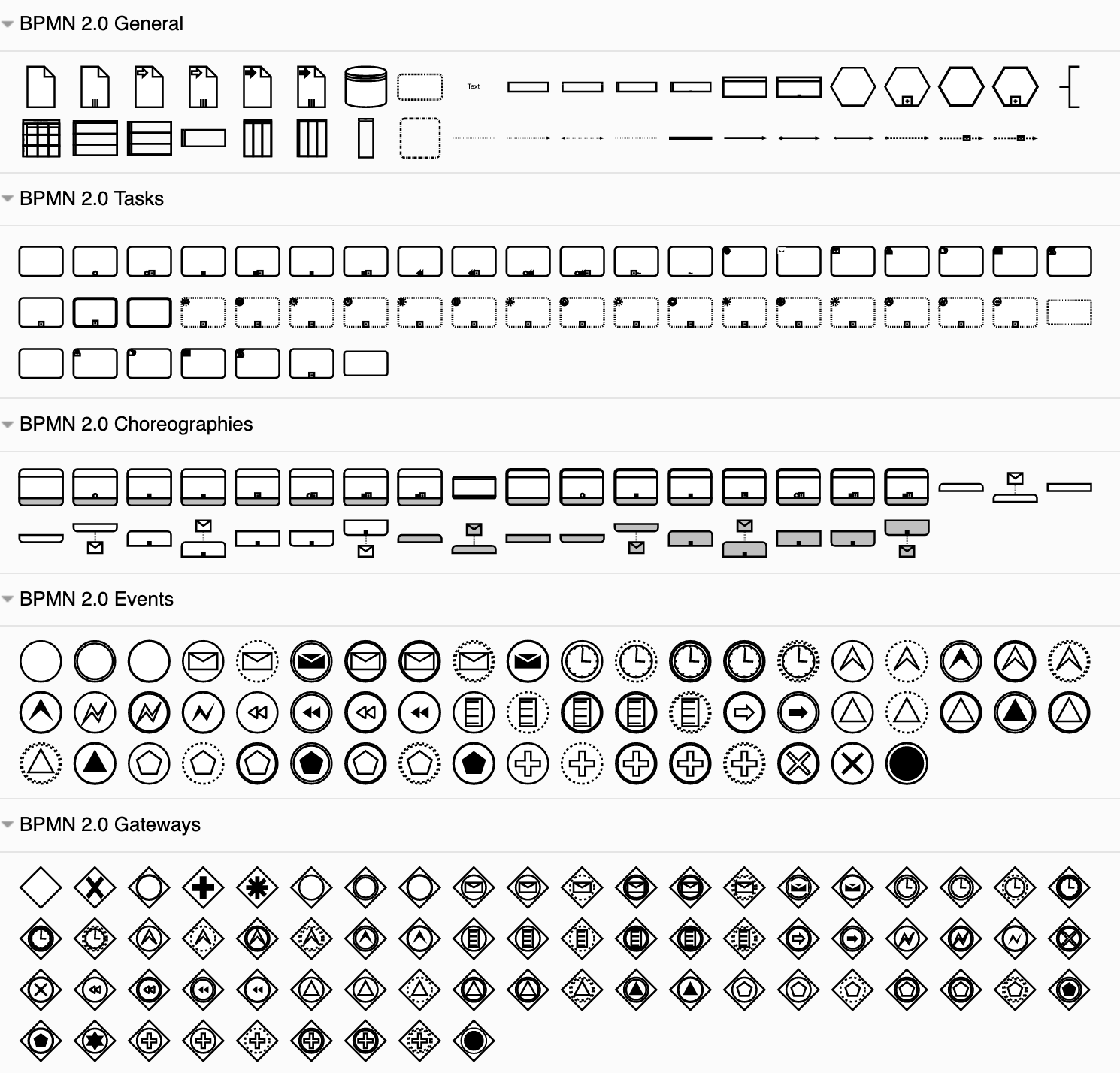
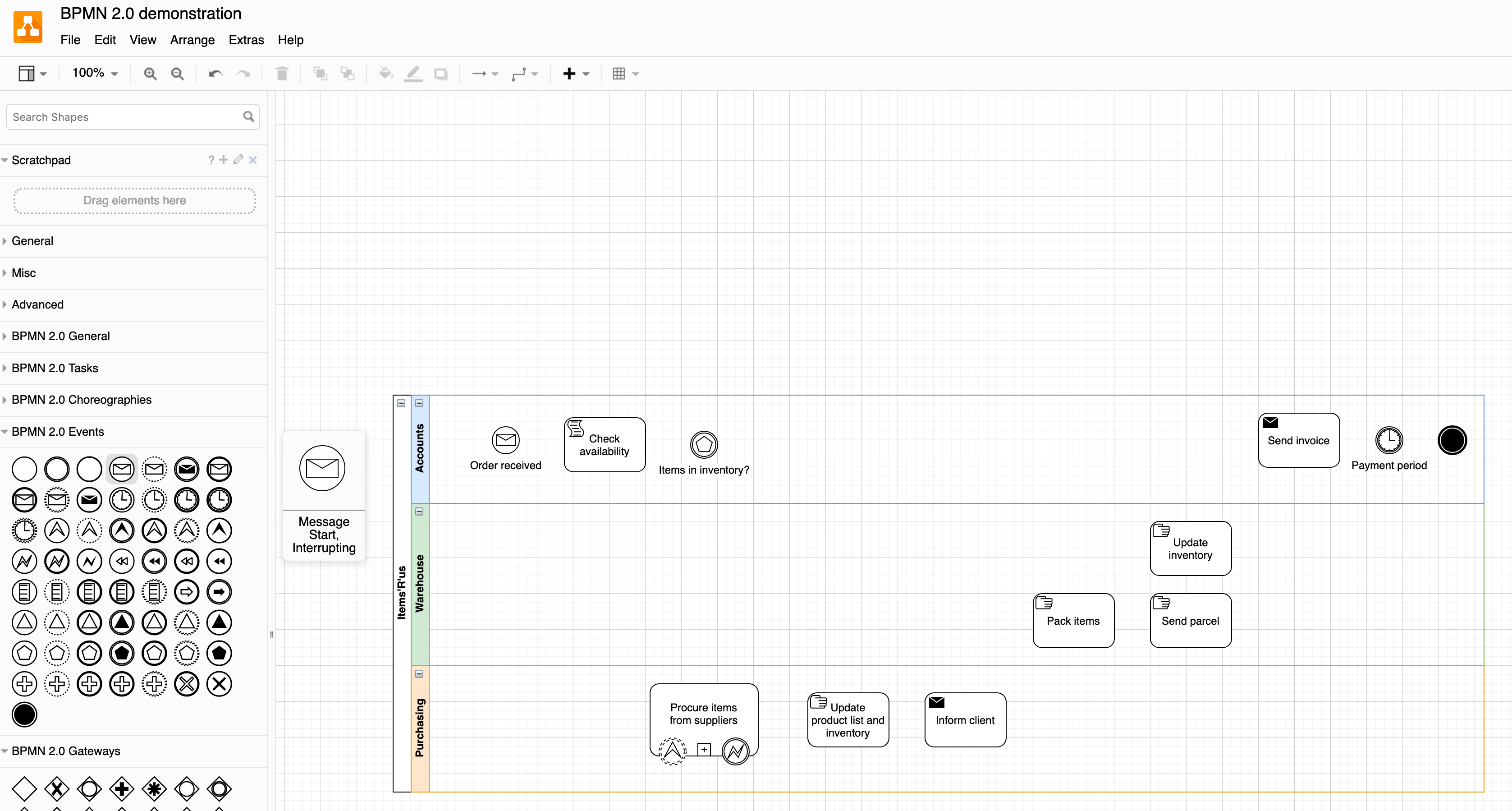
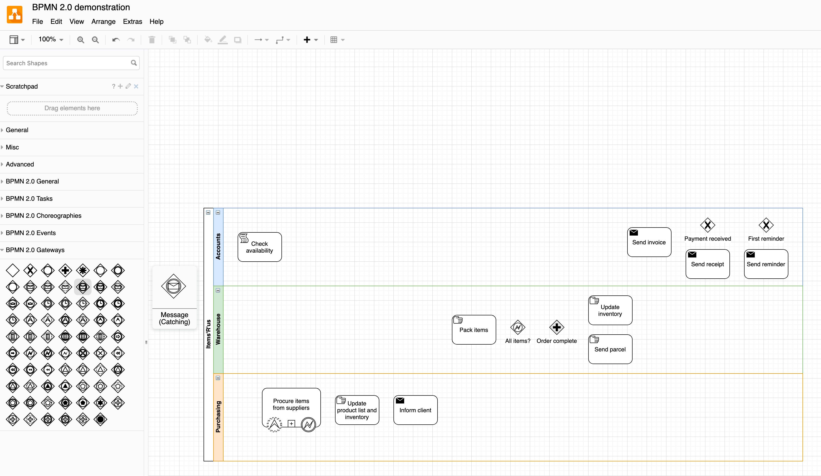
Tip: To see what each shape in the BPMN 2.0 shape library represents, hover over it, and a preview with a tooltip will appear to the right of the shape library panel.
The BPMN standard is well structured. The main components in a BPMN diagram are detailed below.
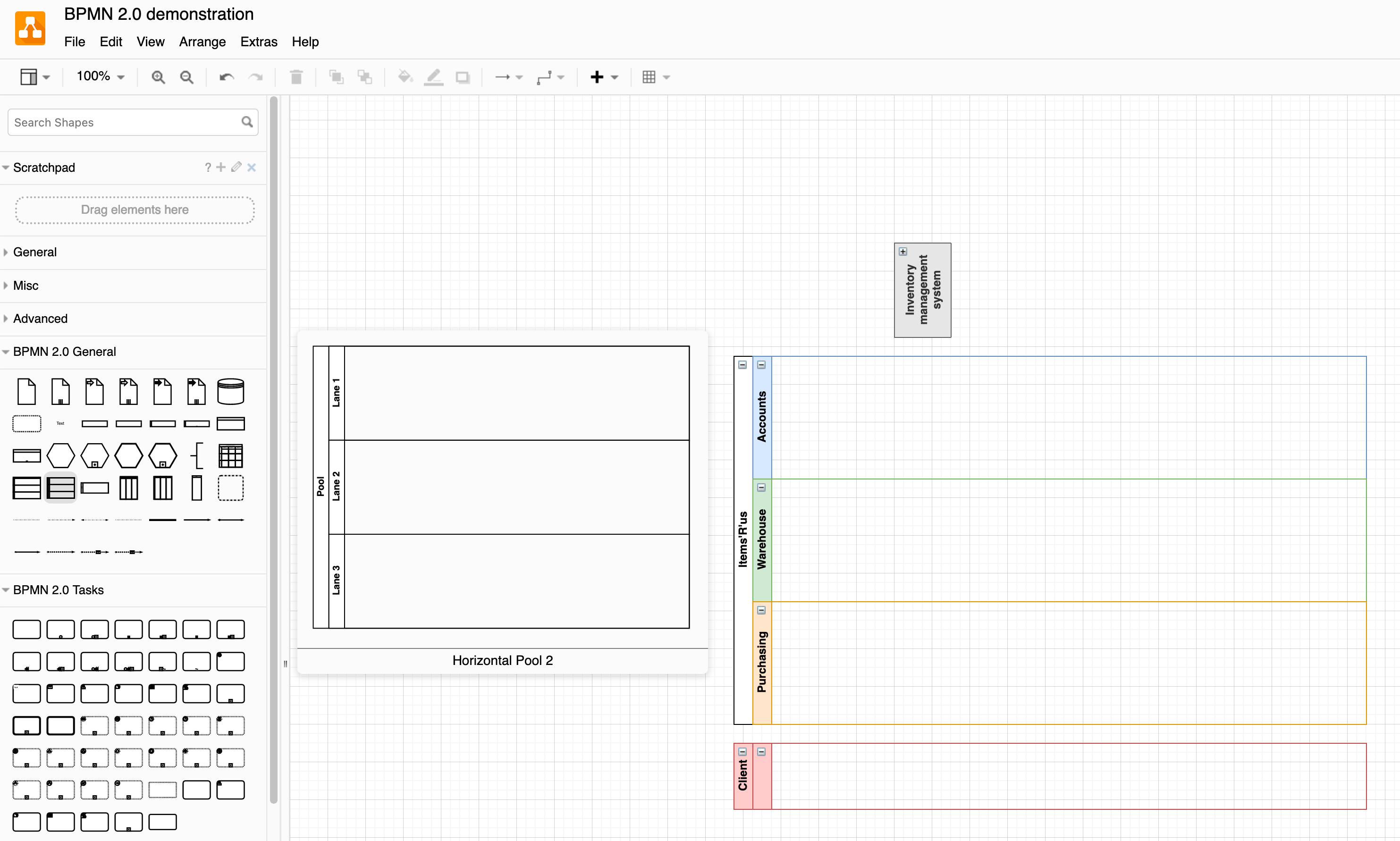
Pools and swimlanes
Business processes are more easily understood when the steps in the flow are grouped under those roles responsible for implementing them. Pools and swimlanes indicate areas of responsibility or roles.
Pools: Whole organisations or collaborations that contain swimlanes. Pools can be collapsed and the tasks within them hidden when those particular steps don't matter or are out of the scope of the process.
Collaboration diagrams detail the process steps in all pools, noting when communication occurs. Basic BPMN diagrams will usually only detail the process steps in one of the pools.
Swimlanes: Specific roles are defined by swimlanes inside pools, and tasks distributed to those responsible for their execution.
Swimlanes and pools can be horizontal or vertical. You can also use a cross-functional table shape to describe more complex areas of responsibility.
Select a swimlane and press Alt+Enter to duplicate it, or Delete to remove it. Add and remove swimlanes to and from pools using the Table tools in the Arrange tab of the format panel, or drop a new swimlane shape into the pool.
Activities
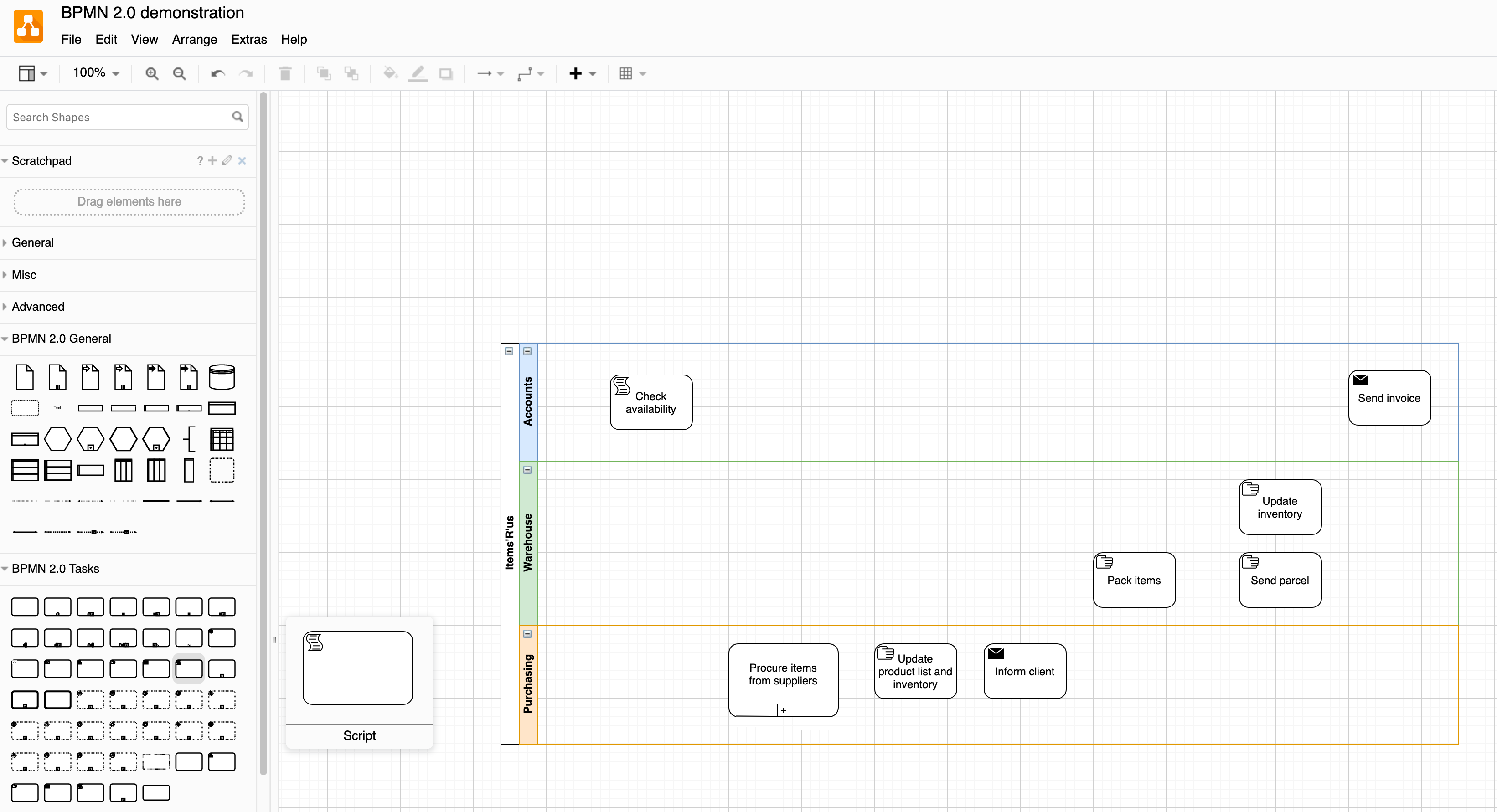
Tasks are the basic steps taken by the people responsible.
Complex tasks, or sub-processes, are indicated by a + at the bottom of the task shape. You can link these shapes to another page in your BPMN diagram, if you would like to model the sub-process individually. These individual tasks, usually performed within one swimlane, often omit the swimlane and pool.
Tasks can include identifiers which specify their type - this makes it easy for new stakeholders to quickly read and understand your BPMN diagram.
You don't need to include every single task or step, only the ones that are important.
Events
Events that occur within the flow of tasks are indicated by various symbols inside circles. Symbols that are filled or unfilled, or which have thick/thin/dotted outlines, indicate different forms of the event, such as whether a timer is interrupting or not. This was one of the additions to the BPMN 2.0 version.
Sub-processes (complex tasks), may have event ports - simply overlap an event on the task shape.
Gateways
Gateways represent decision points, and branching or merging. Like events, there are many different reasons for decisions or branching, represented by different symbols inside the gateway shape's diamond outline.
Gateways can be exclusive (or), inclusive (and/or), parallel (and) or event-based. The flows or connectors leaving a gateway should be labelled.
Data
Databases and documents or data generated from a task are represented by various shapes in the BPMN 2.0 General shape library in draw.io. Pools can also represent data-heavy systems (such as inventory management systems, or ticketing systems) that don't require human input to complete their tasks.
Connectors
Sequence flows connect tasks, events and gateways, always in the order of execution. These are represented by solid connector lines with a solid arrow head. Sequence flows never cross over to another pool - this would be represented by two sequence flows, one in each pool, passing messages where necessary.
Message flows depict the communication that happens between two different pools with a dotted line. At the source event or task or gateway, the message flow connector has a round head, and at the target, an unfilled triangle.
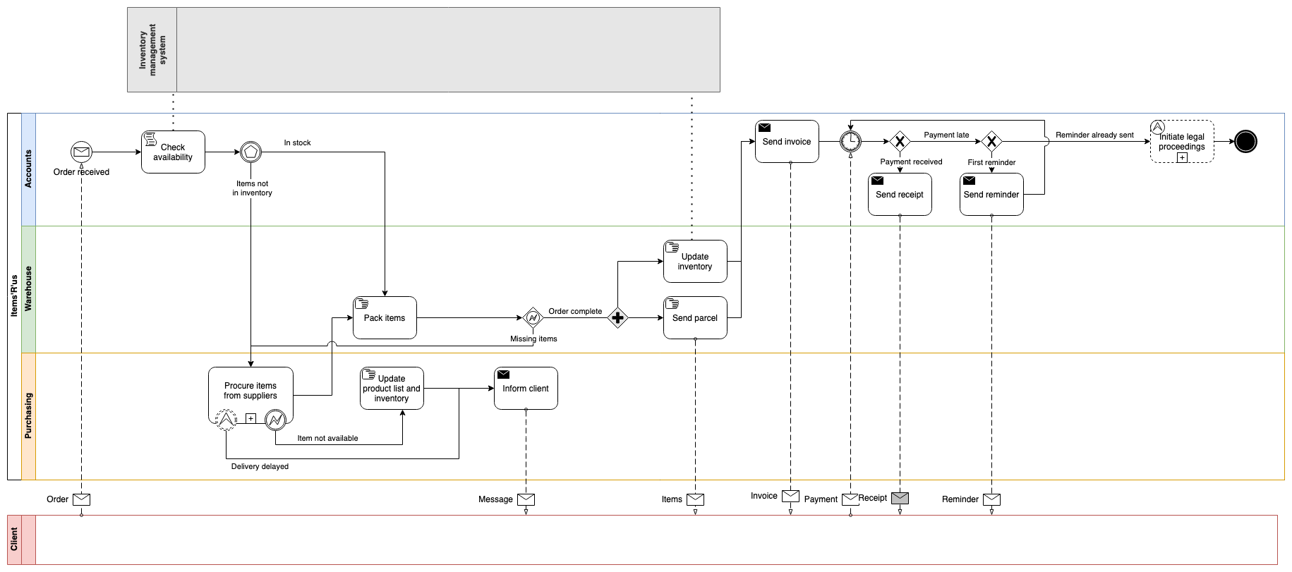
Open the example BPMN 2.0 diagram in the draw.io editor
You can find both styles of connectors in the BPMN 2.0 General shape library, along with connectors with the letter icon, or you can style connectors you drag to connect existing shapes on the drawing canvas.
Orchestration, choreography and collaboration models
Orchestration: models a process within a single business entity, represented by a pool.
Collaboration: models the communication between business entities, across the pool boundaries.
The example BPMN diagram above is a combination of an orchestration (task order) and a collaboration (message passing) model.
Choreography: models the interaction between people, focusing on the message flow between two (or more) roles. Choreography tasks usually include the sender and receiver within the task shape itself, instead of grouping them into swimlanes. This was the biggest change introduced in BPMN 2.0.
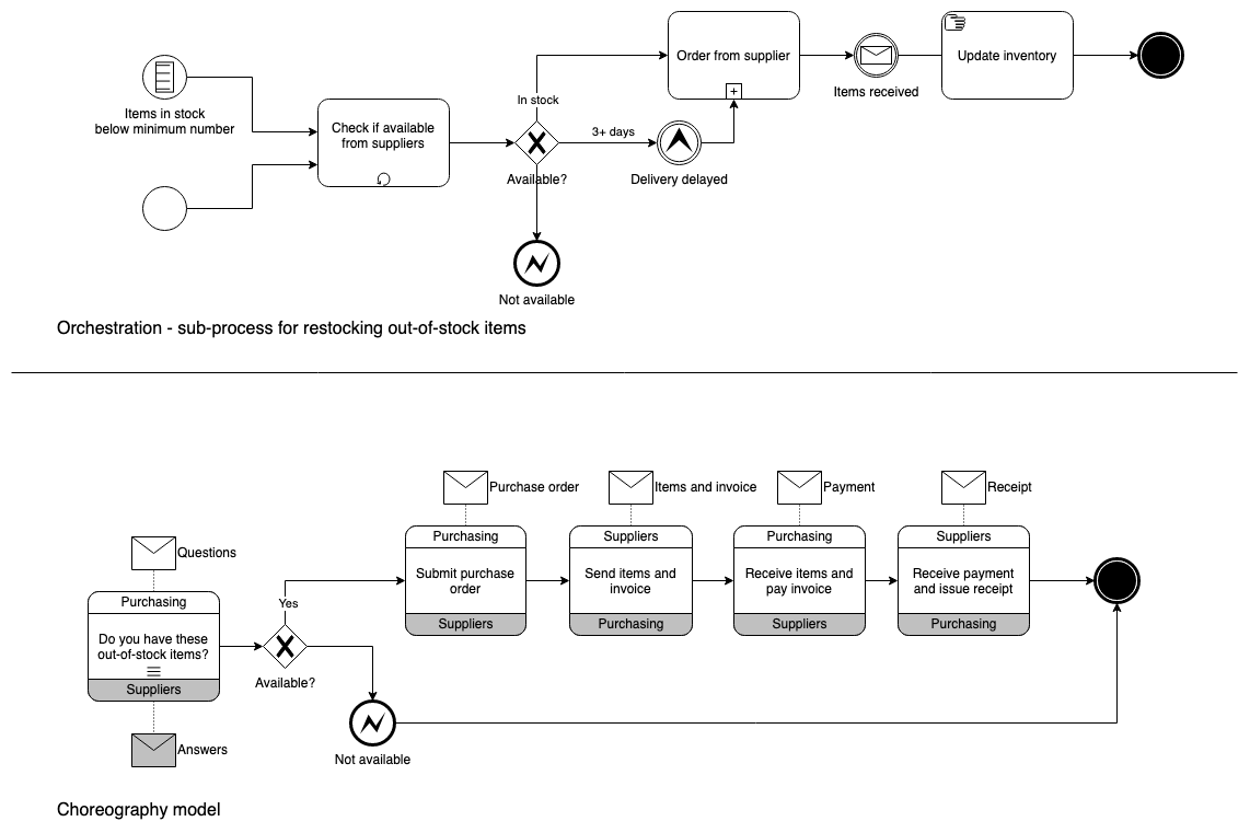
Open this example BPMN 2.0 choreography model in the draw.io editor
Tip: You can also create a conversation model using the conversation shapes in the BPMN 2.0 General shape library in ddraw.io.