SysML vs UML - what's the difference?
Systems modelling language (SysML), is an extension of UML that has been modified for systems engineering. While both can document software, information and processes, SysML diagrams also document the hardware, humans, physical components, and facilities in the system.
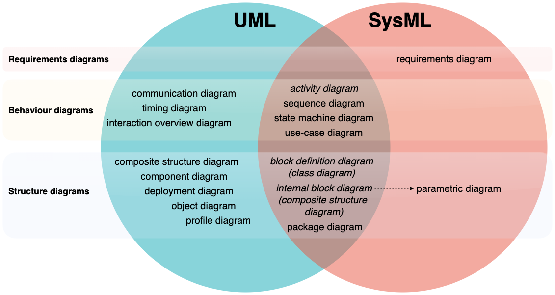
SysML has fewer diagrams than UML, and modifies three of the shared diagram types: activity diagrams, block definition diagrams (from class diagrams), and internal block diagrams (from composite structure diagrams).
Two new types of diagrams in SysML - requirements and parametric diagrams - are used to document specifications and ensure the system and illustrate how the product will meet measurable performance, safety or quality criteria.
Tip: Use a multi-page diagram
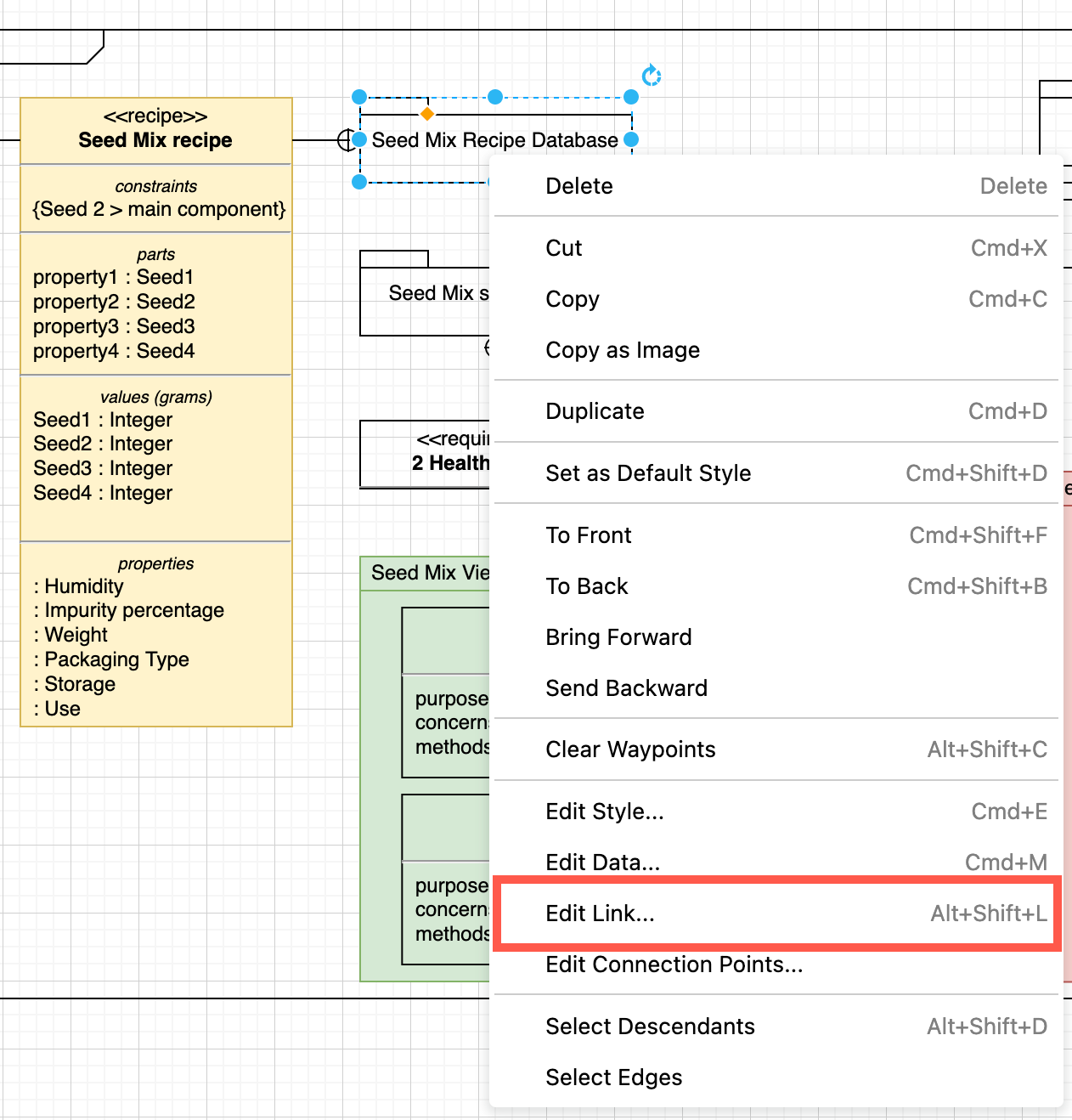
As each system or component may contain sub-systems/sub-components, use multi-page diagrams and link the parent shape to its detailed diagram page. Select a shape and press Alt+Shift+L, or right click on a shape and select Edit Link .
Enable the SysML shape library
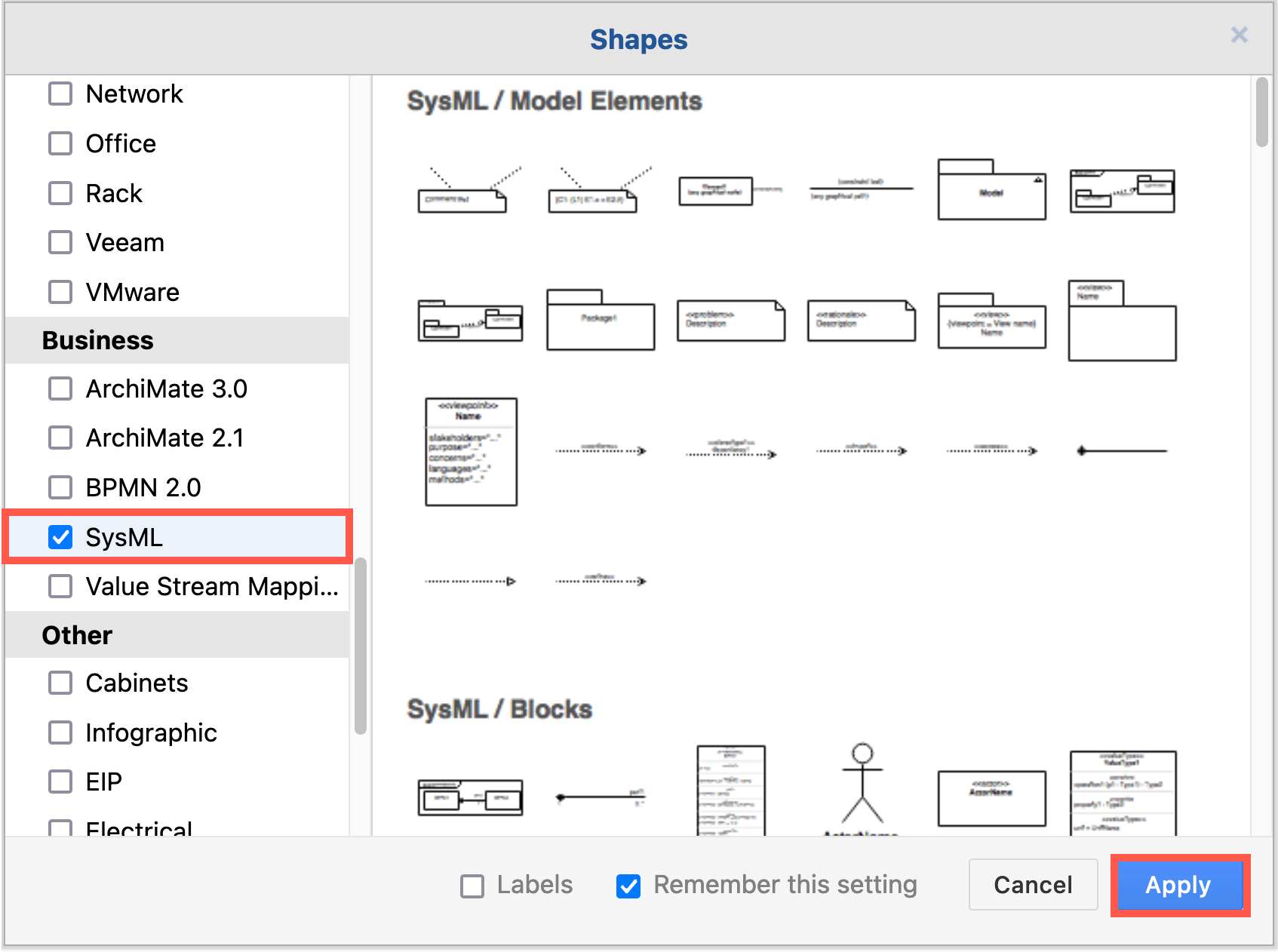
To create SysML diagrams in draw.io, enable the SysML shape library. The shapes are organised into diagram-type sub-categories.
- Click on More Shapes at the bottom of the shape panel on the left.
- Enable the checkbox next to SysML in the Business section.
- Click Apply.
While you could create many of the diagrams with the UML shape libraries, the block shapes with ports, constraints and flows are in the SysML shape library.
Tip: Style the shapes with colour to more clearly differentiate between types of elements, different groupings or regions.
SysML diagrams for systems engineering
Many of the SysML diagrams are the same or very similar to their UML counterparts - this is noted when each diagram type is introduced below.
Requirements diagrams
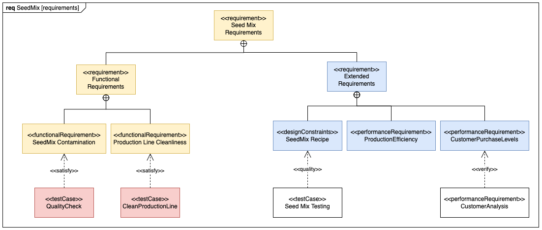
SysML requirements models are created early in the process to define and refine customer requirements. (SysML only)
Also called detailed specification diagrams, requirements diagrams show how the different requirements are related to each other and design elements. They include descriptive test cases to ensure requirements are tracked and met during implementation.
Requirements can be specified as:
- functional - these requirements must be met.
- non-functional - a quality criteria to test and evaluate the performance of a system and whatever it outputs.
Non-functional requirements can be specialised in the following ways.
<<performanceRequirement>><<interfaceRequirement>><<designConstraint>><<physicalRequirement>>
Contained requirements are indicated with a circle with a vertical cross at the parent requirement. Test cases and derived requirements are linked to requirements with a dashed connector and an appropriate label.
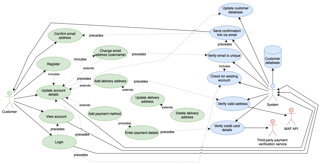
Use-case diagrams
A use case diagram all of the ways an end-user interacts with your systems. (Same as UML)
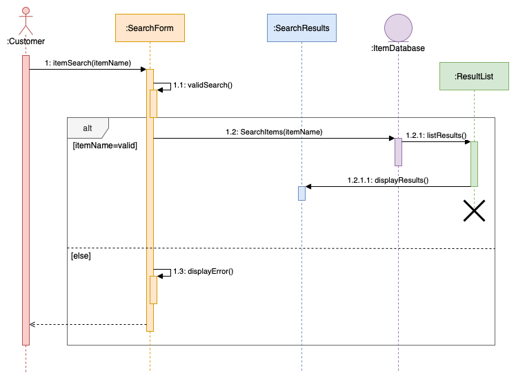
Sequence diagrams
Sequence diagrams show the order of messages that are passed between the elements of a system to complete a particular task or use case. (Same as UML)
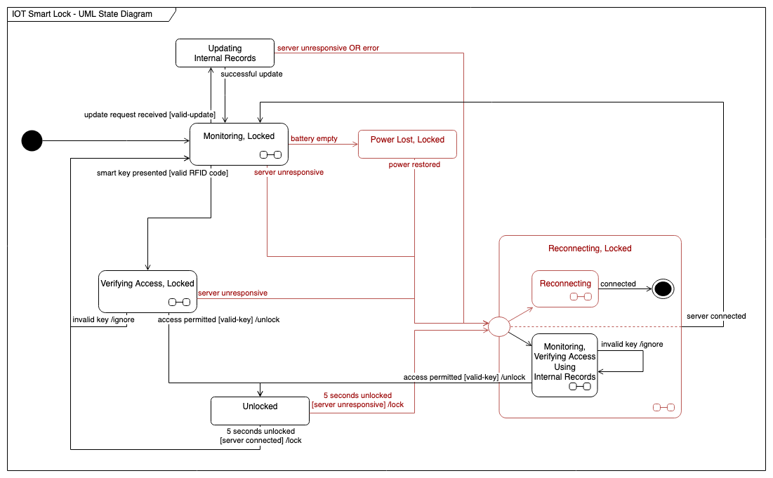
State machine diagrams
State machine diagrams document the various states a system can reach. Each node shows a system state, and the connectors show the triggers that force a change to another state. (Same as UML)
Activity diagrams
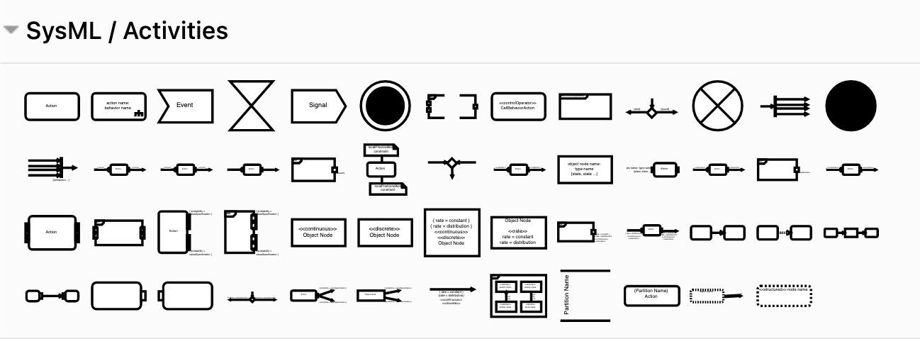
Activity diagrams in SysML use slightly different shapes to those in UML, but the concepts are the same.
In SysML activity diagrams, steps showing both the flow of control (solid connector) and the flow of data (dashed connector) are arranged into swimlanes. Regions can show events, group sub-activities, or note interrupts.
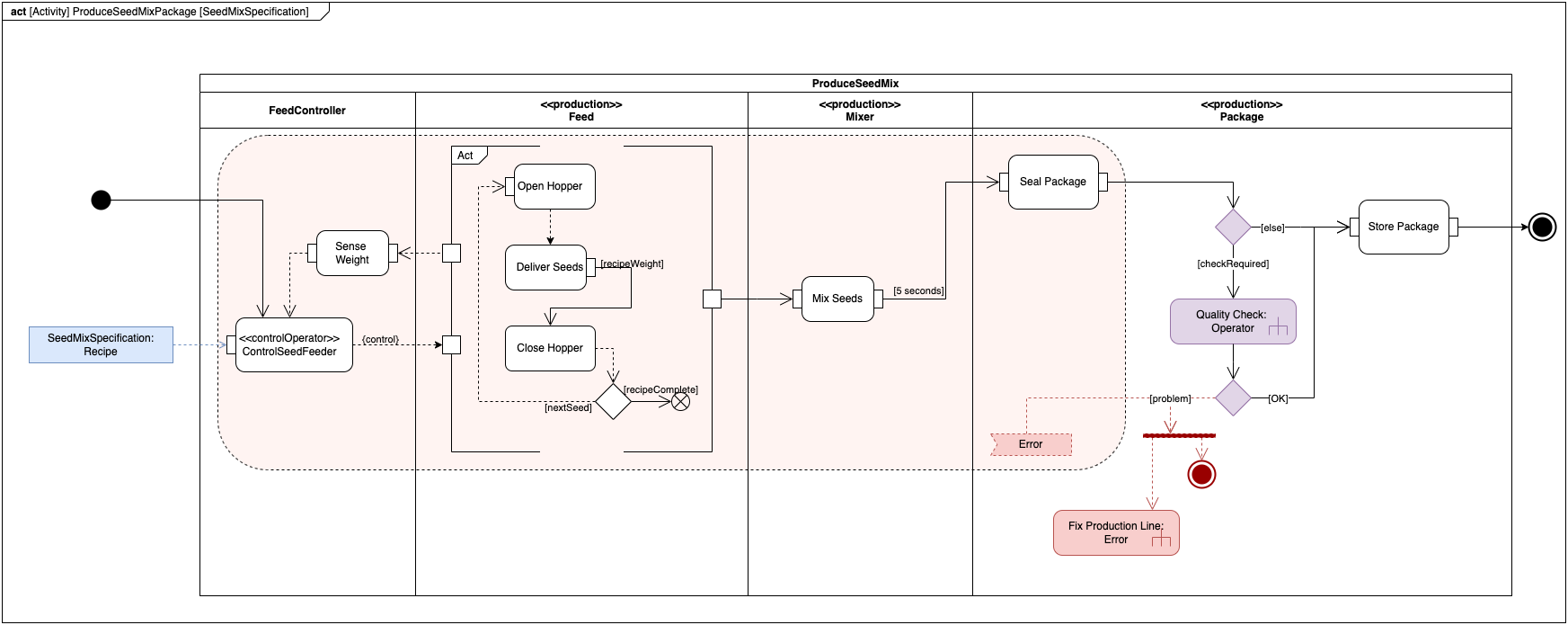
Use the shapes in the SysML Activities category to build your activity diagram. The ports on activity shapes - the small squares - specify where data parameters or objects are required.
Package diagrams
SysML package diagrams are slightly different to UML package diagrams.
Package diagrams are used to document, organise and manage large and complex systems. From this overview, you can link to lower level diagrams for sub-packages, operations (activity diagram), constraints, blocks, and so on.
Use shapes in the Model elements category, and place them to form logical groups inside each package, including views and viewpoints, models and model libraries, constraints, and requirements where required.
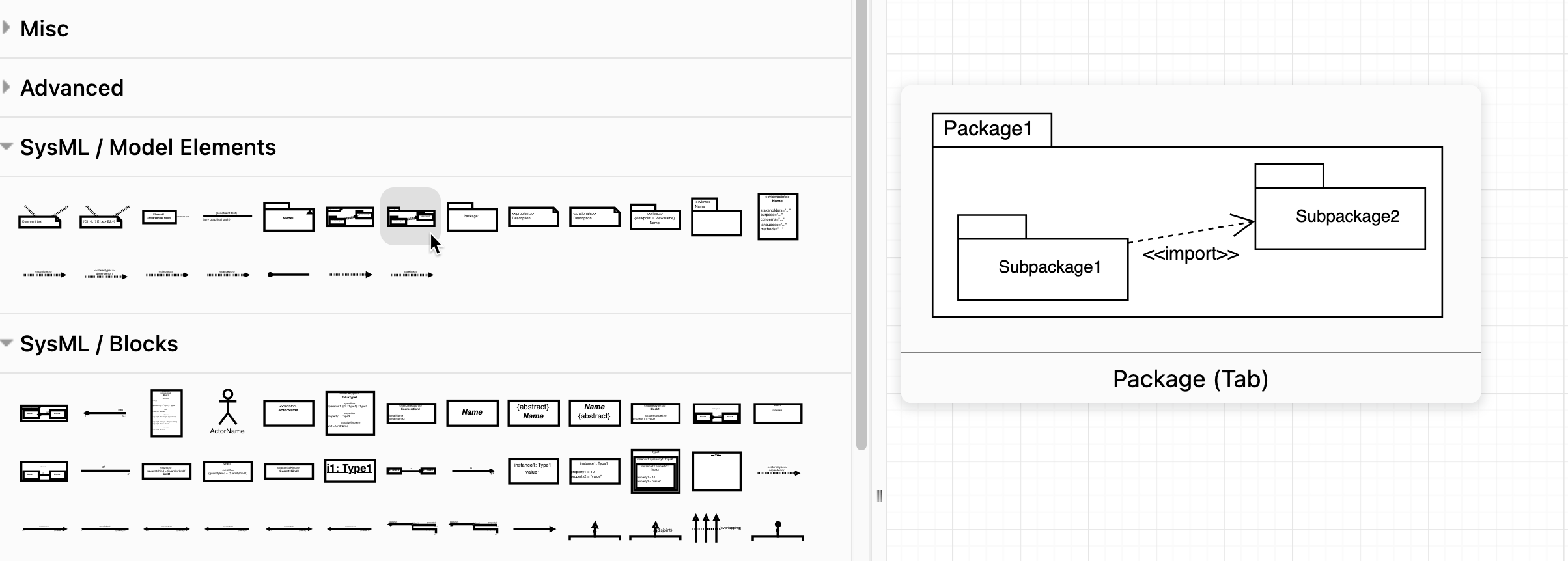
Use the Package Diagram as the outer shape to name the diagram. SysML Blocks shapes can also be used in package diagrams.
Relationships between packages and elements are shown with different connector ends and solid or dashed lines: depend, import, realize, conform, contain, refine, and expose.
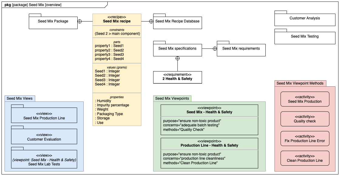
Tip: Label any unclear relationships by double clicking on a connector, e.g. <<conform>> or <<refine>>.
Many of these shapes can contain sub-diagrams. Alternatively, create a multi-page diagram and link from the parent shape to its page.
Block definition diagrams
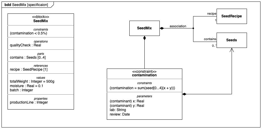
SysML block definition diagrams are heavily modified UML class diagrams.
'Blocks' describe the architecture of a system and contain constraints, operations, parts, references, values, and properties - everything you need to specify the hardware, software, and human components of a system.
One or more compartments - stereotype, namespace, and structure - may contain lower level block definition diagrams, nesting simpler systems inside higher level blocks.
Connectors indicate behaviour similar to UML class diagrams, but with fewer 'arrow' types:
- dependency - dashed line
- association - middle label with an arrow to indicate association direction
- part association - filled diamond
- shared association - empty diamond
- generalisation - empty triangle
- namespace containment - circle with horizontal/vertical bars
Connectors can split to form multi-branch associations. Use the waypoint shape to join these connectors neatly in draw.io.
Work with text in block shapes:
-
Press
Enterto add a new line. -
Double click on a word to highlight and format it with the Text tab on the format panel.
-
To add a section divider, highlight an existing divider in any block shape. Double click on target block so you can see the text cursor, and press
Ctrl+CthenCtrl+Vto copy and paste the section divider at that location.
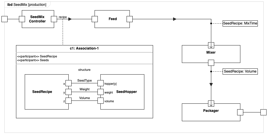
Internal block diagrams
SysML internal block diagrams are modified UML composite structure diagrams.
Internal block diagrams describe connections between the ports of block instances to show what data or material flows between those blocks and its properties.
There are some special types of properties:
- ports - permit only specific types of interactions with that block
- constraints - limit other properties inside the block
- participants - indicate composite associations
Connectors in internal block diagrams can show the following:
- dependency - dashed line
- binding - solid line, optionally with tye type indicated, e.g.
<<equal>>
Indicate flow directions with solid arrows - basic filled triangle shapes - in the middle of the connectors.
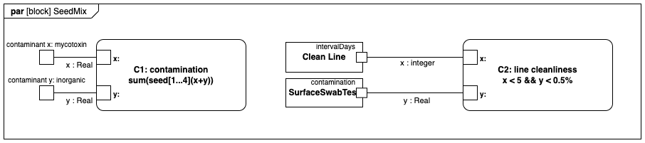
Parametric diagrams
A parametric model is a specialised form of internal block diagram used to analyse metrics for performance, safety, reliability, and measurable physical characteristics. (SysML only)
Link each constraint via its ports to either a constraint parameter node or another constraint shape. Use the shapes in the Constraints and Ports and Flows categories, and modify, flip and label them as needed to suit your layout.
Tip: Overlay additional square shapes to add more than two constraints and group them with the constraint shape. Hold down Alt or Option to overlap shapes on container shapes.