UML activity diagrams
UML activity diagrams show the sequence of actions and the flow of control in a system or a process. You can model the behaviour of physical and digital systems, as well as business process flows with activity diagrams.
UML activity diagram template in draw.io
Activity vs sequence diagrams
Sequence diagrams show the message flow between objects. They show a detailed timeline of the sequence of messages passed and received.
Activity diagrams show the flow of control in a process - the order of execution of actions to complete that activity. They are similar to basic flowcharts and are easy to draw and read.
Activities in interaction overviews
Activity diagrams are often used as part of interaction overview diagrams. Store all of the diagrams in one multi-page diagram and link from the overview page to each detailed activity or sequence diagram.
Draw activity diagrams in draw.io
Go to our online version of draw.io or open the draw.io desktop app or any of our integrations to create a new activity diagram.
Enable the UML shape libraries
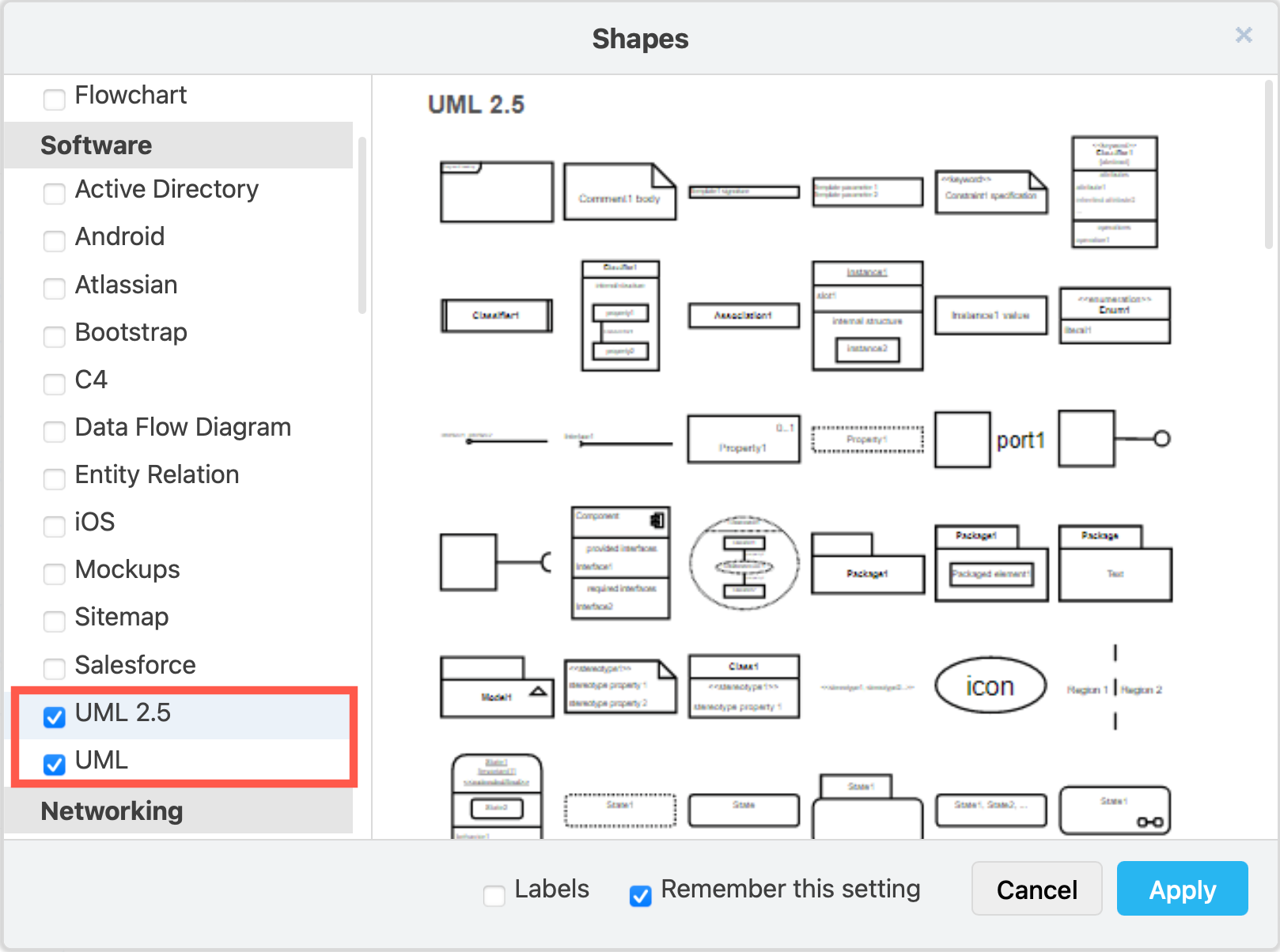
- Click on More Shapes at the bottom of the left panel.
- Enable the UML 2.5 and UML shape libraries in the Software section.
- Click Apply to return to the diagram editor.
Use an activity diagram template**
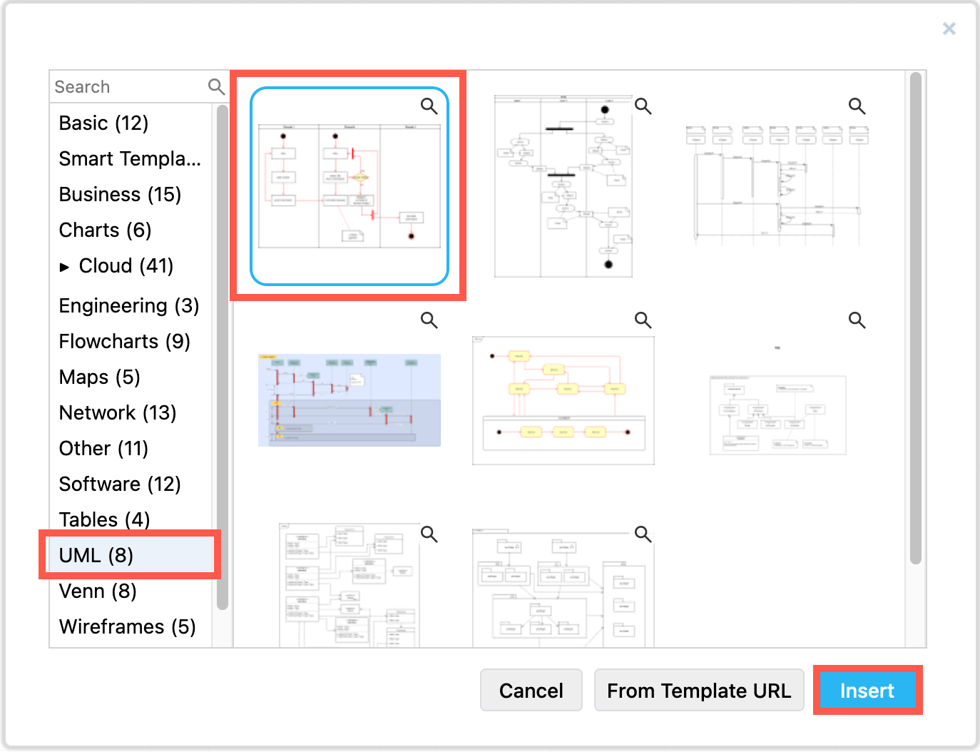
- Select Arrange > Insert > Template from the menu.
- Select the UML category, then select an activity diagram template.
- Click Insert to add the template to the drawing canvas.
UML activity diagram symbols
The shapes used to draw activity diagrams are similar to those use to draw simple flowcharts.
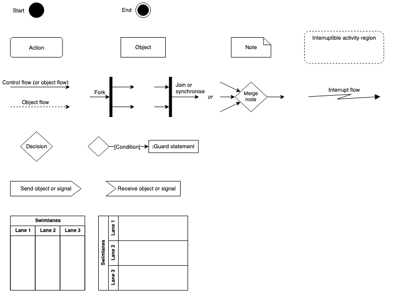
Shapes used in UML activity diagrams - open this reference in our diagram viewer
Shapes
- Start: solid circle.
- End: solid circle inside another circle.
- Swimlanes: container shapes with multiple collapsible lanes, vertical or horizontal, from the Advanced shape library. These are called partitions in the UML standard.
- Drop a shape into a swimlane when the outline is purple to add it to the lane. If you move that swimlane to another position or resize it, the shapes it contains will move with it.
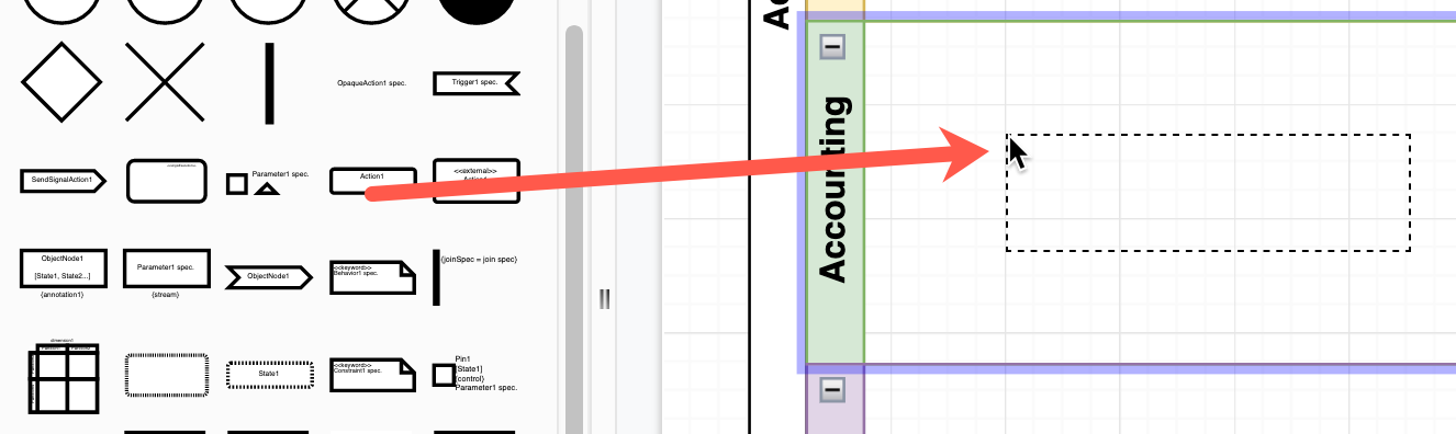
- Hold down
AltorOptionas you drop to overlap the shape without adding it to the lane. - Finally, drag connectors between the shapes - you can connect to shapes in other lanes.
- Drop a shape into a swimlane when the outline is purple to add it to the lane. If you move that swimlane to another position or resize it, the shapes it contains will move with it.
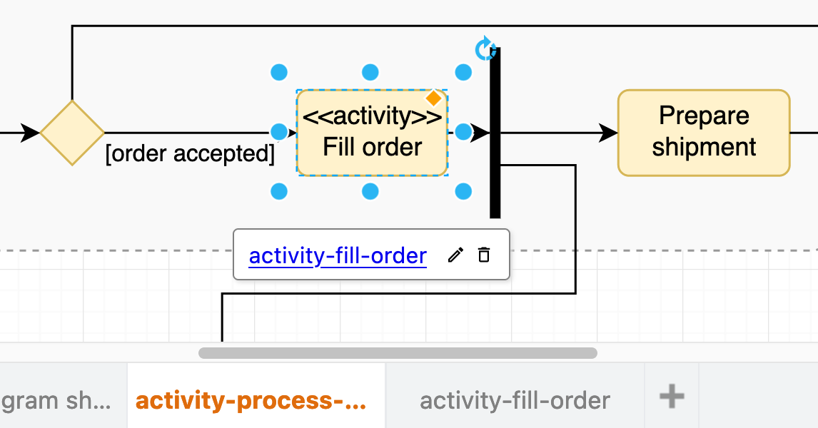
- Action: rectangle with rounded corners, may link to detailed sub-activity diagrams on another page within the same diagram.
- Object: rectangle with square corners, to hand an object to another action.
- Note: comment shape - a rectangle with a folded corner.
- Interruptible activity region: large rectangle with rounded corners and a dashed outline. This region surrounds actions that are allowed or able to be interrupted. Move this shape to the back via the Arrange tab in the format panel.
Flow connectors in activity diagrams
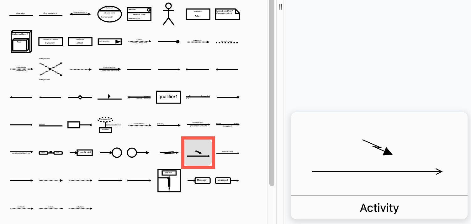
- Control flow: solid connector arrow.
- Object flow: (optional) dashed connector arrow.
- Fork: solid thin rectangle with one connector coming in and two or more connectors going out.
- Join or synchronise: solid thin rectangle with one or more connectors coming in and a single connector going out.
- Merge: diamond with multiple connectors coming in and a single connector going out. May be used instead of the join shape.
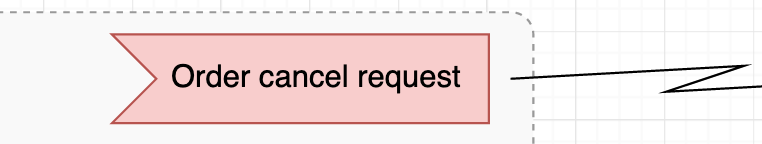
- Interrupt flow: a zig-zag connector coming out of the interruptible activity region. Alternatively, use the straight connector with an interrupting zig-zag shape from the UML 2.5 shape library.
Conditions and decisions
- Decision: diamond with one or more connectors coming out. These may be labelled with the
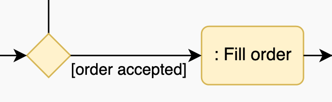
[decision]or[condition]that must be true for the flow to proceed. - Guard statement: rectangle with the condition preceded by a colon. Alternatively, write the colon before the action name and the condition in square brackets on the connector.
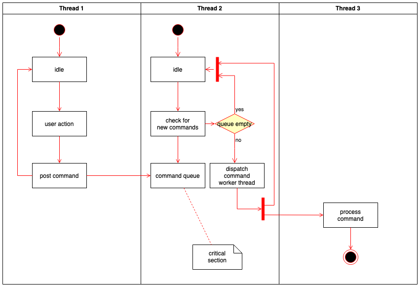
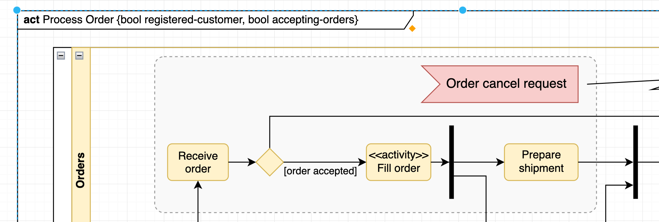
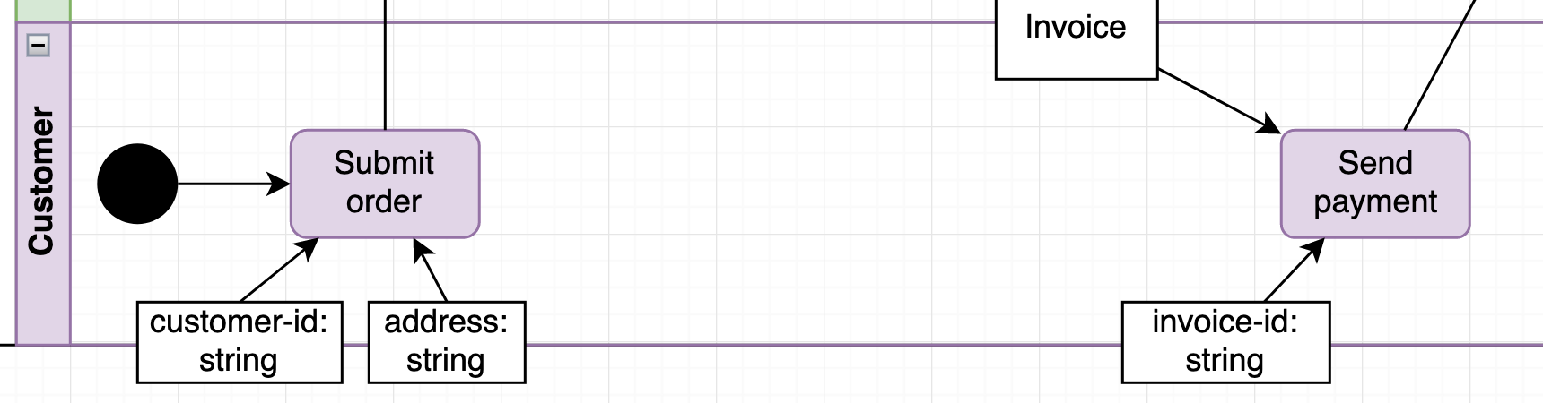
The following activity diagram example details the action steps and flow of control to process a customer's order.
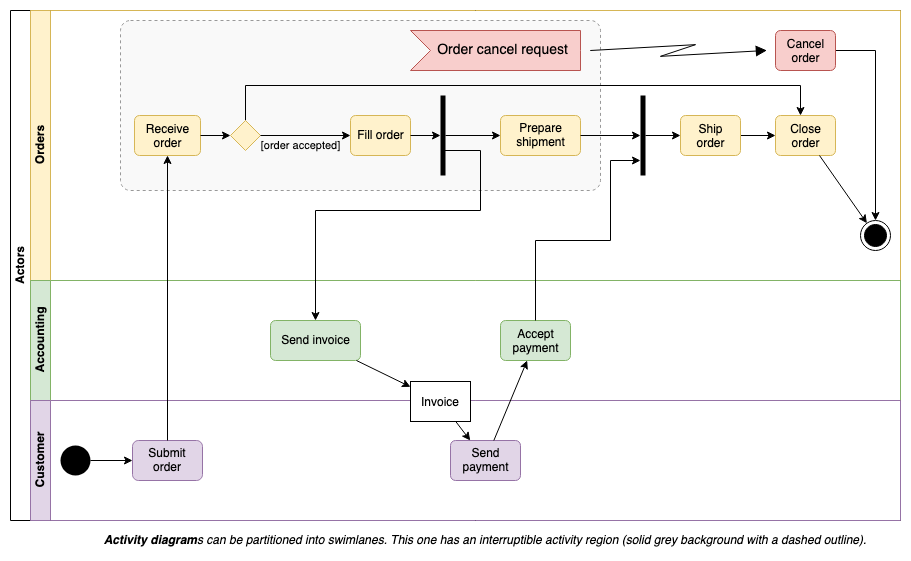
Activity diagram for processing a customer's order - open this in our diagram viewe
Advanced activity diagram symbols
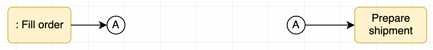
Two small circles with matching letters may be used to continue a flow over a long distance to avoid overlapping connectors or clutter in your activity diagram.
Signals
Use a flag shape from the the UML 2.5 shape library to indicate an interrupt signal or condition and place it inside the interruptible region.
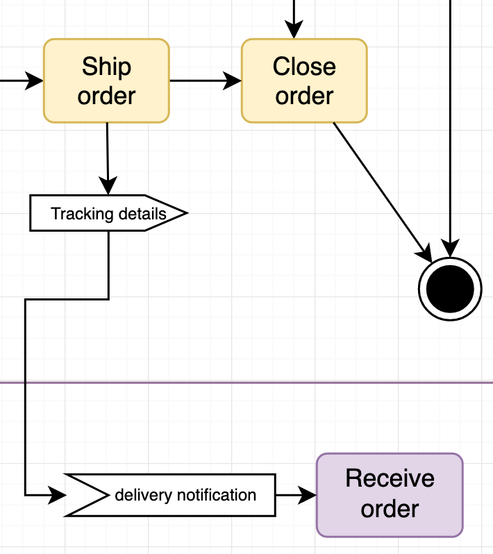
You can also use outgoing or incoming (flag) signal shapes to show that notifications are passed to or received by other actions.
Parameters
Surround your entire activity diagram with the Diagram shape from the UML 2.5 shape library. Alternatively, use a large rectangle with rounded corners.
Write act in the top left to indicate it is an activity diagram, followed by the activity name, and the activity parameters or preconditions in curly brackets. Parameter types are optional.
Use an object shape to indicate action parameters. Types are optional, indicated with :type after the parameter's name.
Additional information
Show constraints and specific details in action, object and swimlane labels.
<<precondition>>and<<postcondition>>for constraints on behaviour-driven actions.<<singleExecution>>for actions that execute only once in a repeating loop of actions.<<external>>for actors who are outside the organisation.<<attribute>>to indicate actor hierarchy in swimlanes.
If you aren't using swimlanes, include the actor in the shape label using brackets. For example: <<external>> (Customer) Submit order
More about UML diagrams
The UML specification allows you to draw many different types of diagrams to model the behaviour and data of a system in different ways.
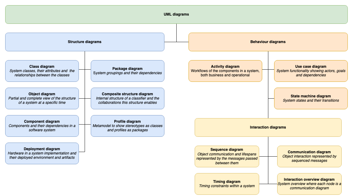
Refer to the UML diagram overview post for details of the many other types of UML diagrams.
Tip: draw.io can also automatically create activity diagrams from text using the Mermaid syntax.