UML use case diagrams
UML use case diagrams show all of the ways an end-user interacts with your systems, with all of its pre- and post-conditions, exceptions and alternate paths. These diagrams are used to establish your system requirements, whether that be a software system or an interaction with another person or team.
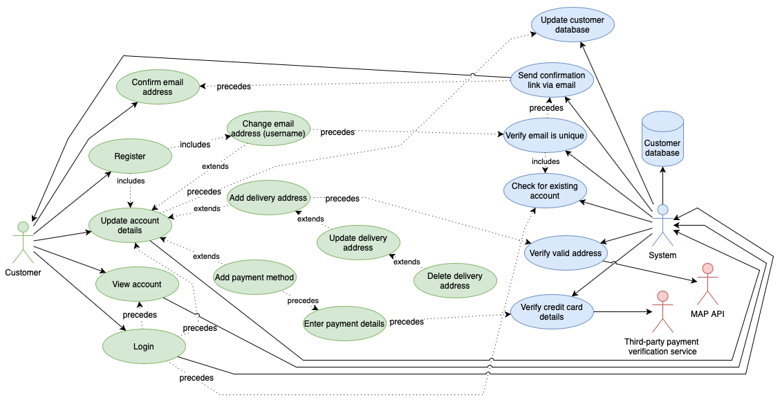
Customer updates their account - open this use case diagram in our diagram viewer
UML use case diagrams are not used for scheduling or broad planning purposes as they are highly technical and specific, but instead function as the foundation for a system's technical documentation.
Each goal or task that a user wants to achieve with your system or program is a separate use case diagram.
UML use case shapes
External actors
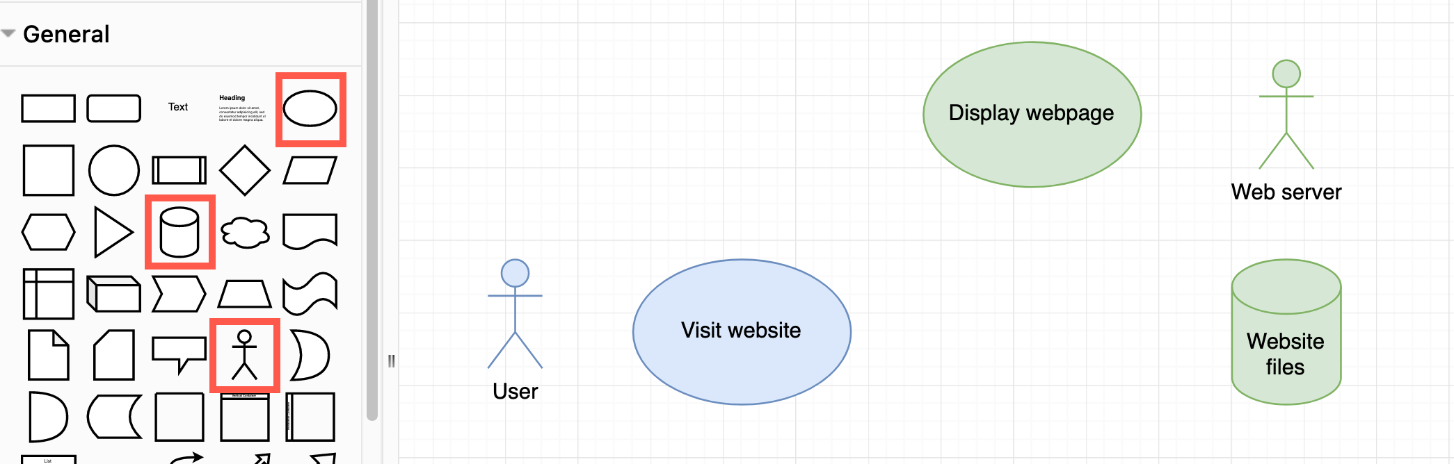
External actors are users (or external processes) that interact with your system. These are typically represented by stick figures, or another shape that may better represent an external system.
Tasks
Actions and tasks are represented by an oval with a verb phrase describing the task as a label.
Data stores
Databases and file systems are typically represented by the database shape.
These shapes are available in the General shape library in draw.io.
Connectors
Draw solid connectors from the actors (or to the actors) represents them performing a task.
Dotted or dashed connectors
Connectors between tasks show a relationship. Use the Style tab to change the connector's Pattern.
- the order the tasks must be performed in with the label
precedes - when a task
extendsor builds upon another task - when a task contains or
includessubtasks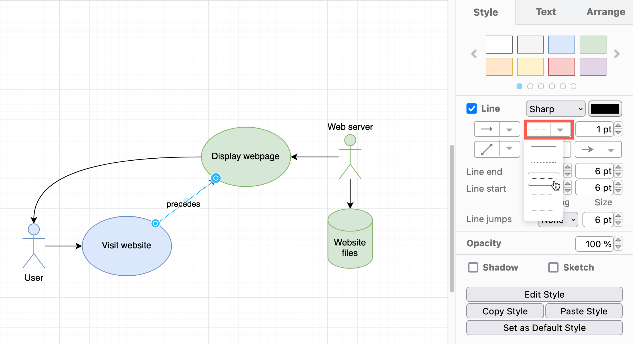
An open arrow head
Connector with open arrows indicate inheritance. You can add a label to this connector to show multiplicity: 1, 1..n or *. Connectors in draw.io can contain three labels - source, target and center labels.
Bounding boxes
Rectangles can be placed to surround a system - uncheck the Fill checkbox in the Style tab in the format panel. Alternatively, use colours and styles to indicate different systems and keep the diagram easier to read.
A diagram frame
The frame shape may surround an entire use case, or leave the initiating actor on the outside, especially when multiple use cases are included in a larger diagram. The use case title is entered into the label in the top left. Use the Frame shape from the UML 2.5 shape library - hover over any shape to see a larger preview.
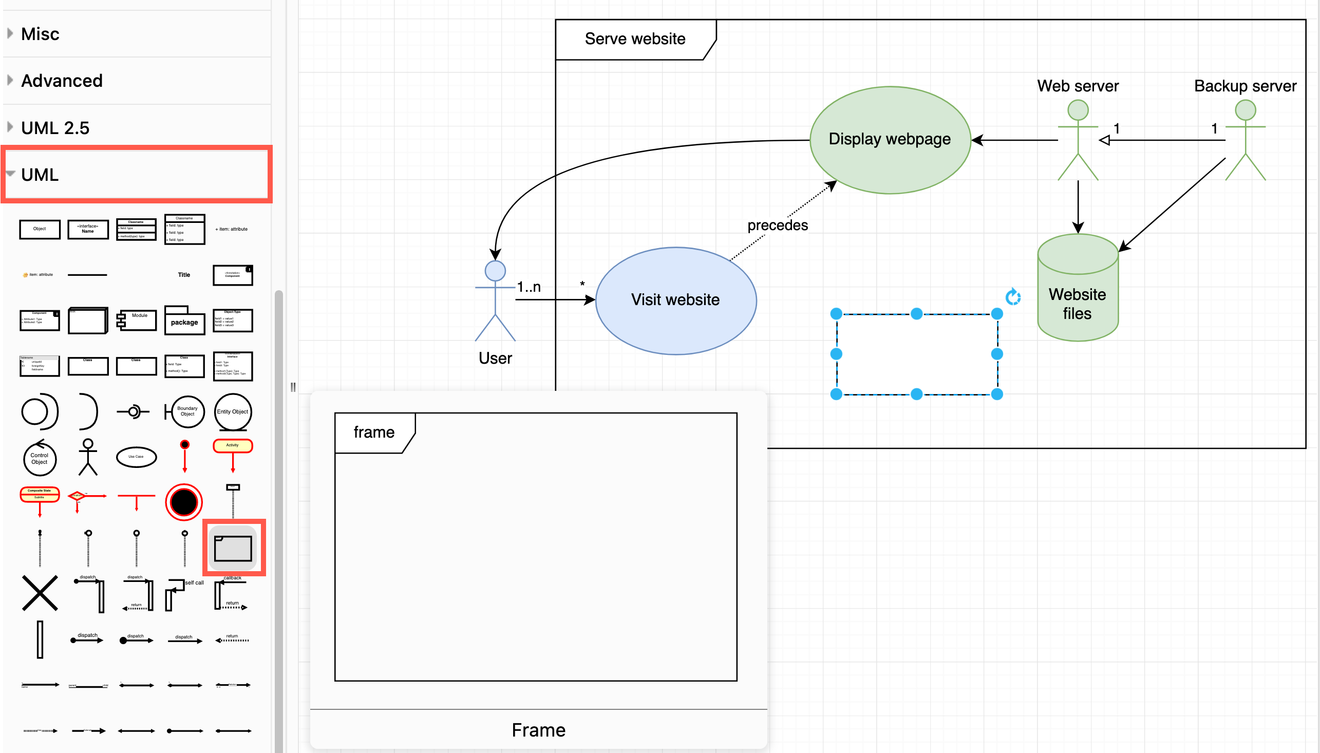
Make sure you send frame and bounding box shapes to the back (select them then press Ctrl+Shift+B) so you can keep working with the other shapes in your diagram.
Using use case diagrams
Improve UX (user experience)
UML use case diagrams are used to ensure a user-centric design of a new system or improve a system to be more user-friendly. They step you through what the user has to do to achieve their goals.
Simplify or reduce external dependencies
You can see where a system relies on external actors in a use case diagram, and what steps interact with those actors. If you find your team is constantly delayed by no fault of its own, draw a use case diagram to pinpoint where the delays occur.
Use case diagrams plus story mapping
In marketing, story mapping captures user stories - what a user or customer needs to do and why - and results in one or more goal phrases, e.g. "As a manufacturer I want to minimise tool changes to optimise production and thus reduce costs". Analyse your system's use case diagram to see which steps can be added, modified or removed so the user can more effectively achieve their user story goal.
More UML diagrams
The UML specification allows you to draw many different types of diagrams to model the behaviour and data of a system in different ways.
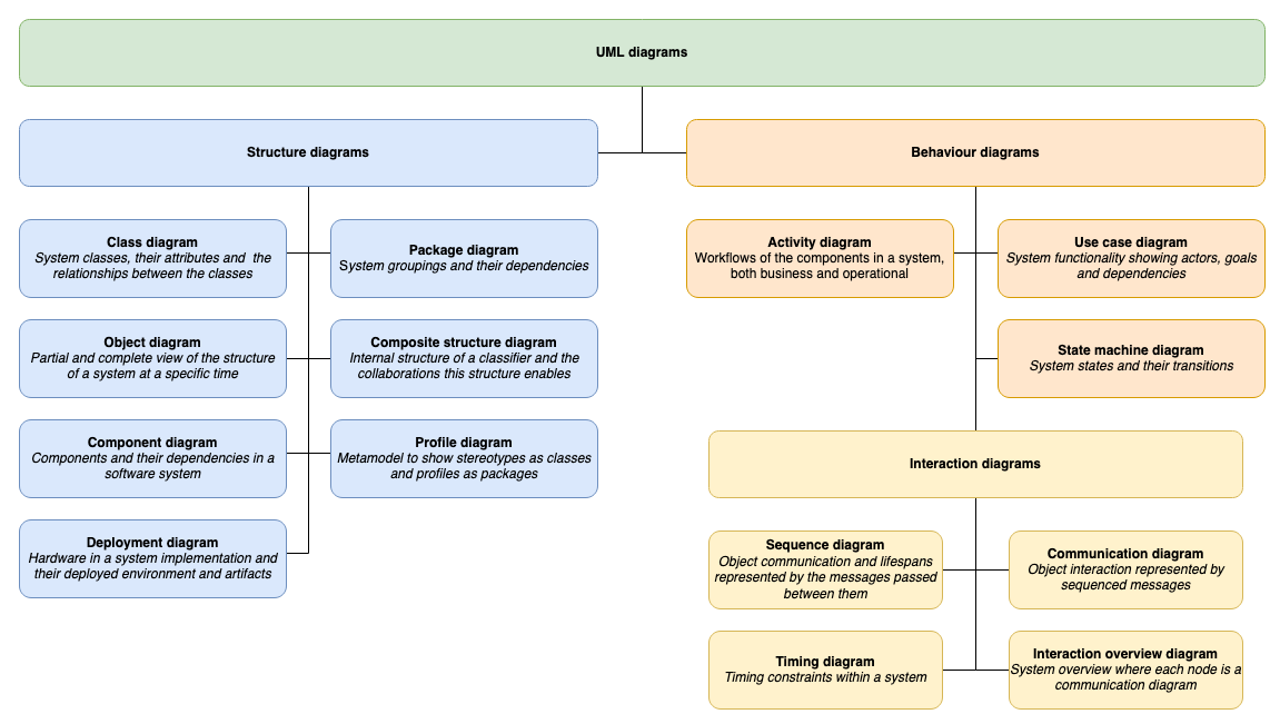
Refer to the UML diagram overview post for details of the many other types of UML diagrams.
Tip: draw.io can also automatically create use case diagrams from text using the Mermaid syntax, or using the diagram generator.