Style connectors
The default connector style is a solid line with an arrow head at the target end.
Select a connector, then use the options and advanced properties in the Style tab, or the connector style tools in the toolbar to change the connector's appearance.
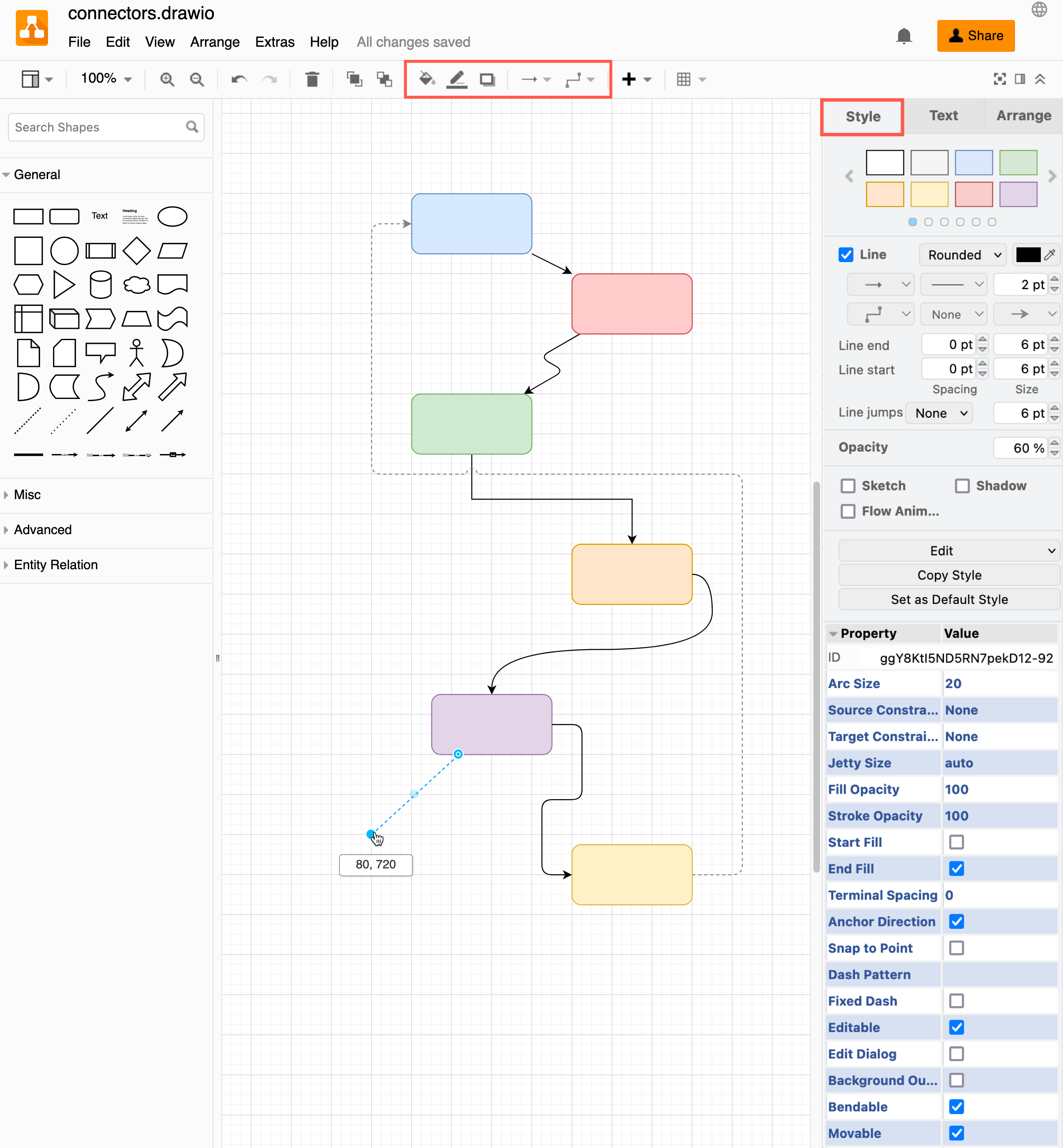
Tip: Copy and paste connector styles using the two buttons in the Style tab of the format panel - Copy Style and Paste Style.
Line style - Styles the 'corners' where a connector changes direction. Choose between sharp (default), rounded, or curved.
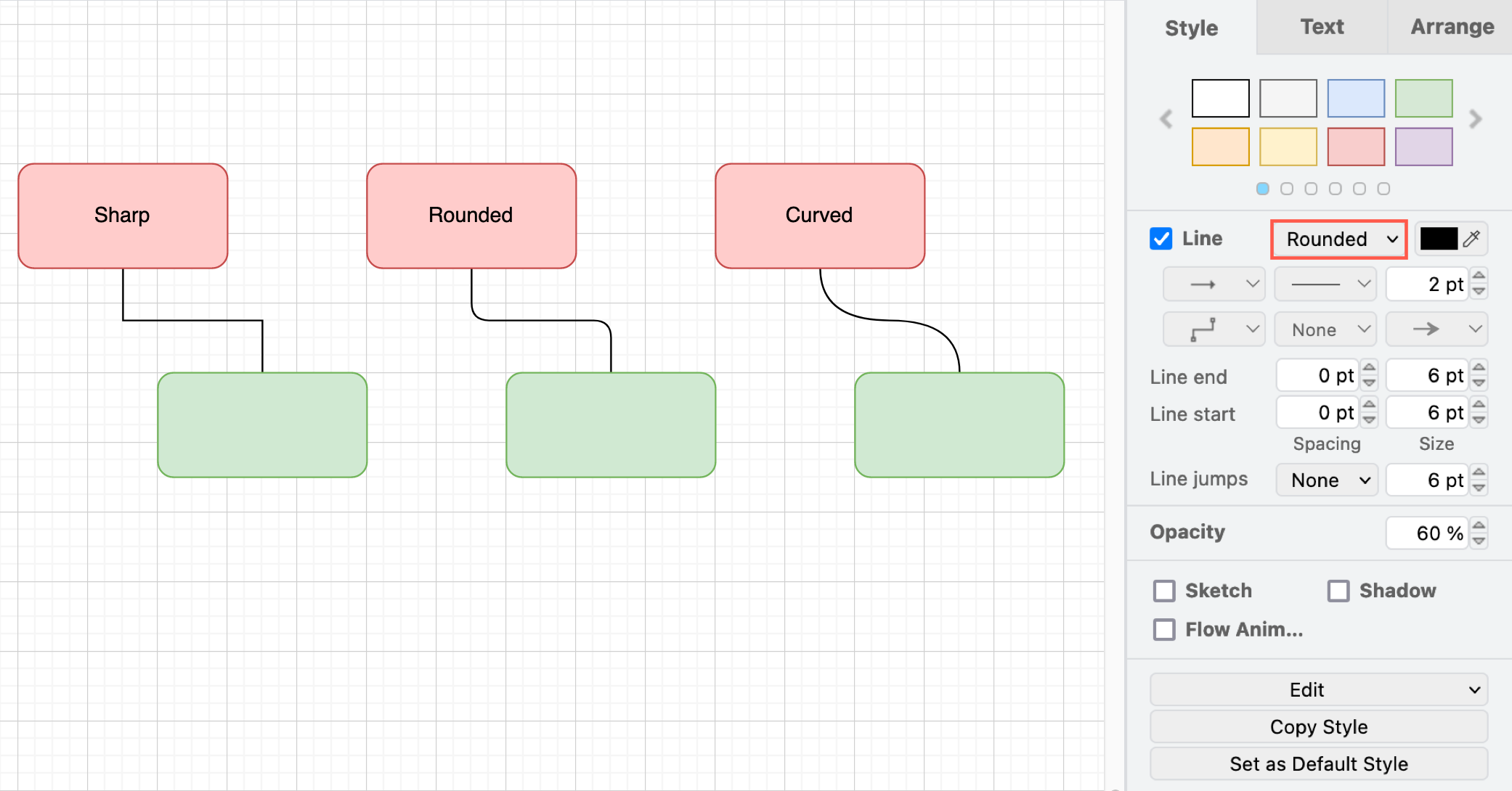
From version 32.2.1 onwards, the labels of a curved connector sit on the curve. This applies to the curved line style and the curved waypoints.
Note: Connectors that were curved before keep their label positions. To move their labels onto the curve, select rounded as the Line style, then select curved again.
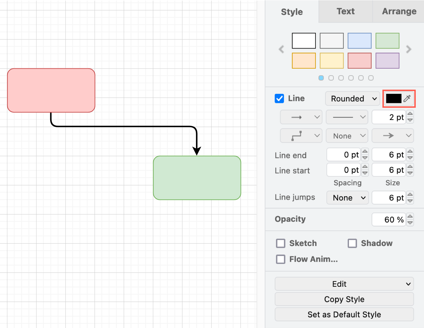
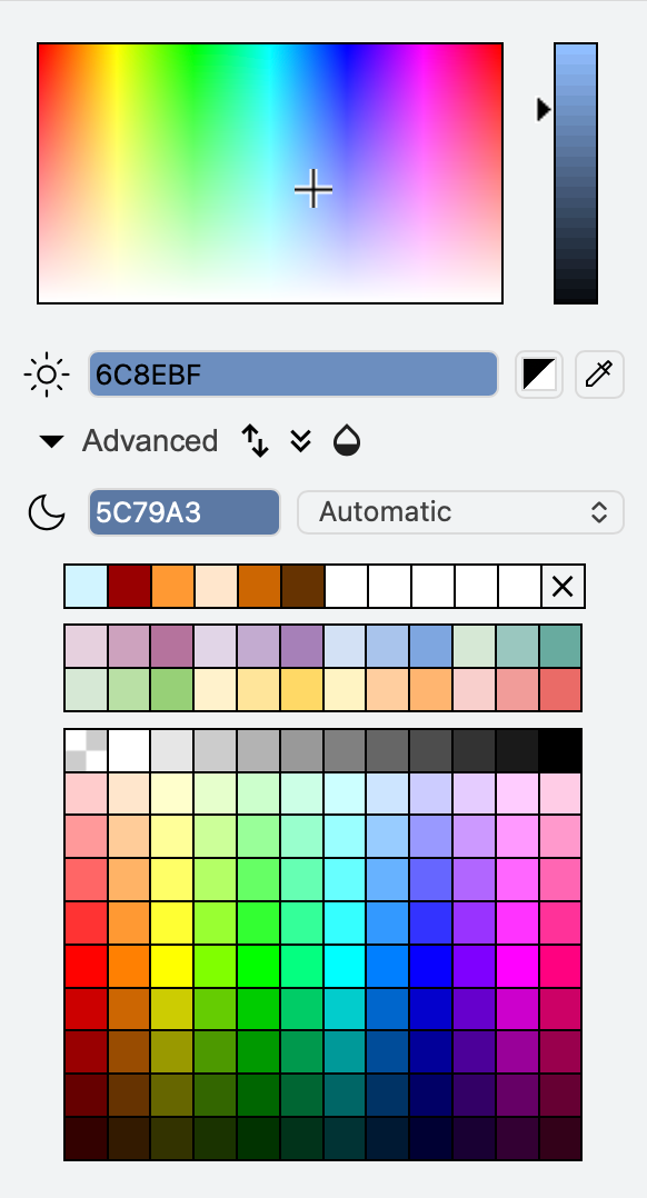
Colour - Change the colour of the connector and its 'arrow' heads with the colour palette. The default is black.
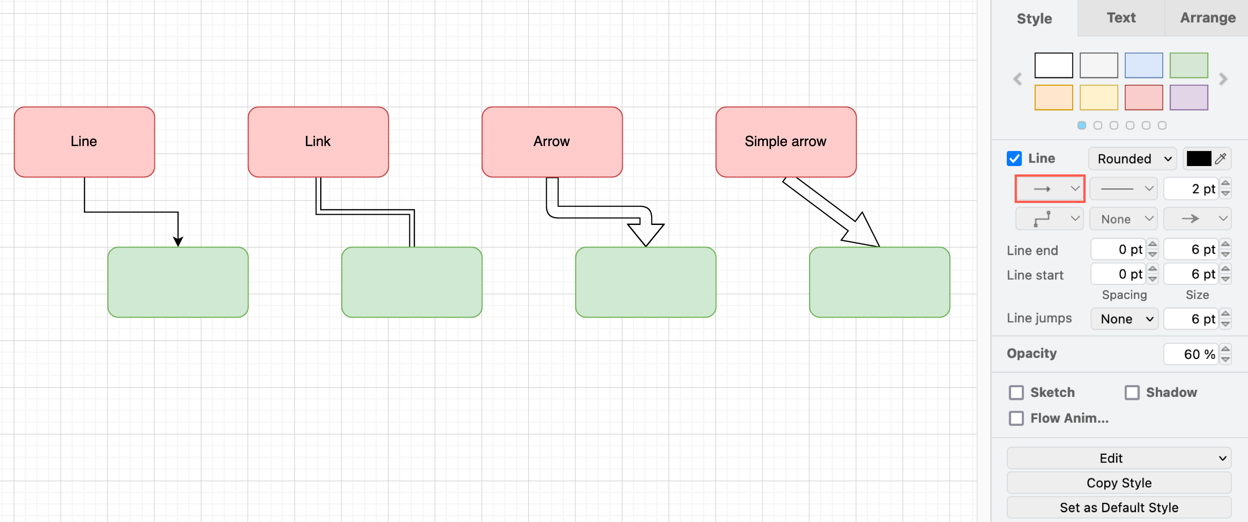
Connection - Turn the default single line into a double line with no arrows (link) or one of two customisable arrow shapes. The simple arrow is a straight connection between the two shapes with no waypoints. The tapered arrow narrows from its source to its target. Set the start and end widths in Arrange > Arrow or drag its two yellow width handles. Add a fill colour or a gradient. The tapered arrow heads will automatically resize to be wider than the line. Alternatively, use the Connection menu to change the connection type in the toolbar, or via in the floating toolbar when you select a connector.
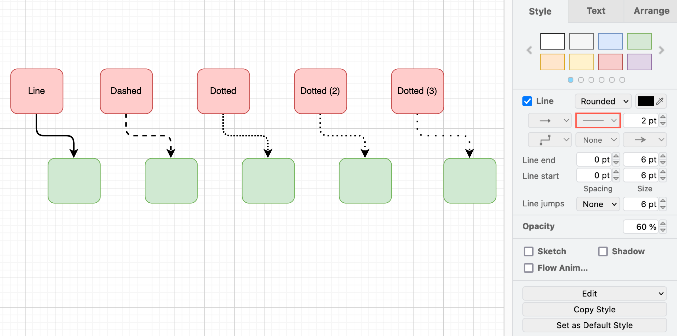
Pattern - Change the default solid line's pattern to a dashed or dotted pattern of varying gap lengths.
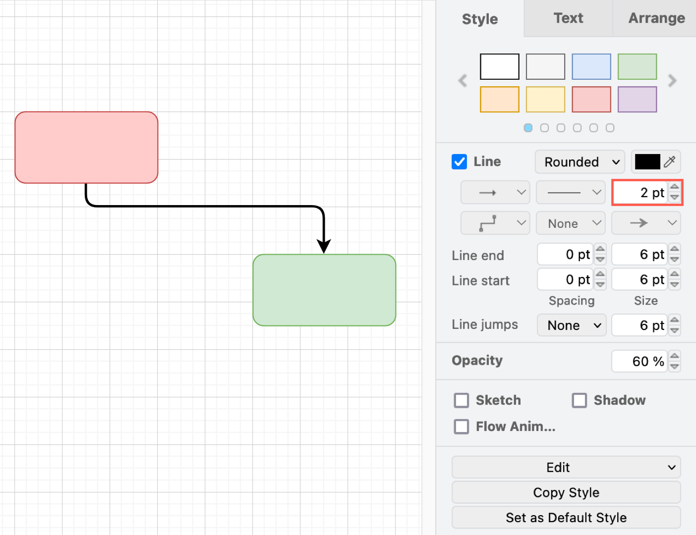
Thickness - Change the thickness of the connector line. The default is 1pt.
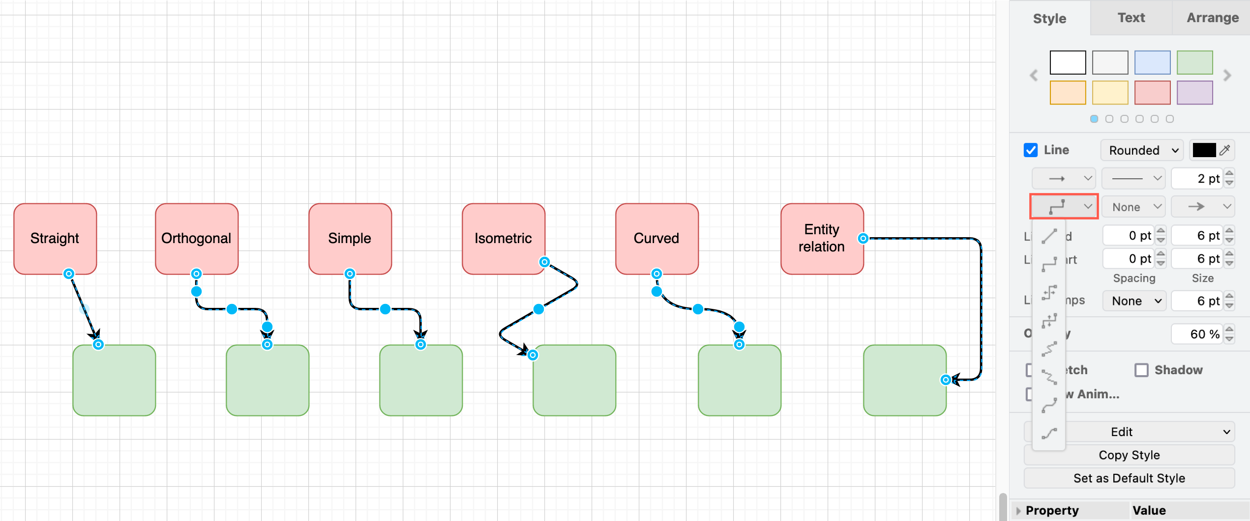
Waypoints - Set predefined anchor points to change the path of the connector between two shapes. Choose between the default straight (no waypoints), orthogonal (with right-angled bends), simple, isometric,curved,entity relation and Auto-route around shapes to route the connector around other shapes automatically.
Work with waypoints on connectors
Source and target 'arrow' heads - Select a connector head from the very large drop down list. There are many different types of arrow heads, as well as symbols for UML and technical diagrams. Choose None for just a plain line.
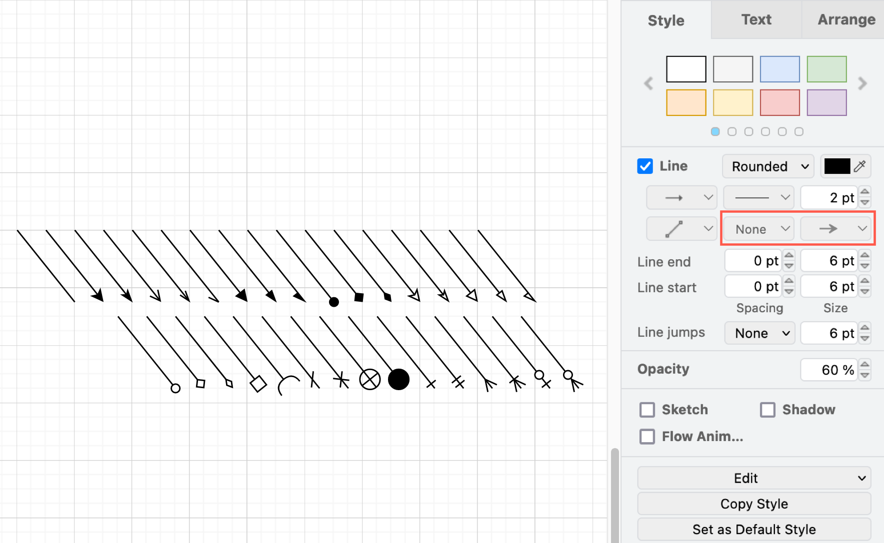
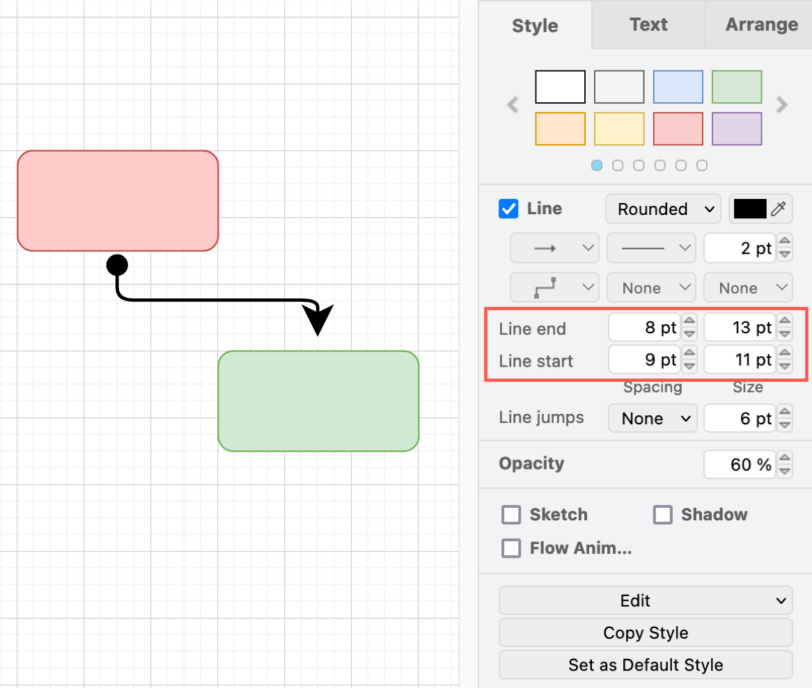
Line end and Line start - Set the Size of the arrow head or symbol, and its Offset from the shape outline. A negative Offset places the end of the connector inside the shape outline. From version 32.4.4 onwards, the former Spacing field is called Offset.
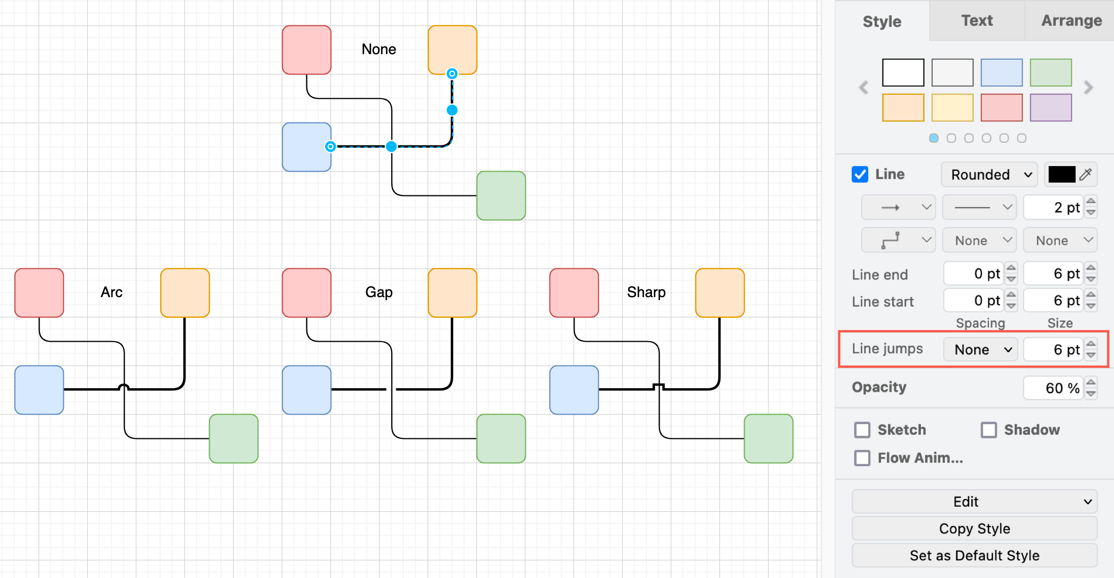
Line jumps - Choose how overlapping connectors should be displayed. Choose between the default overlapped (none), with an arc, a gap or a sharp bend
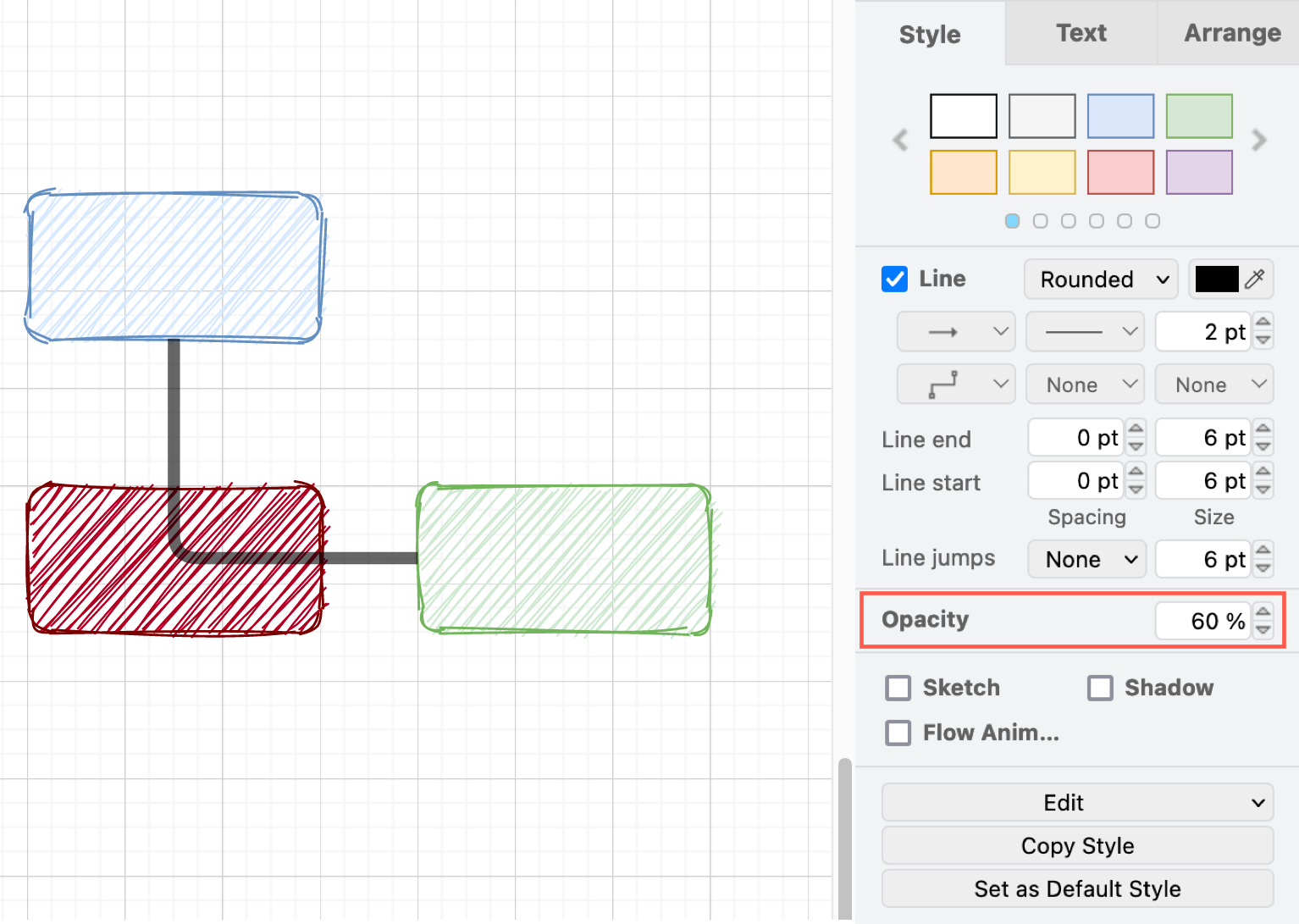
Opacity - Change the Opacity value to allow shapes underneath the selected connector show through.
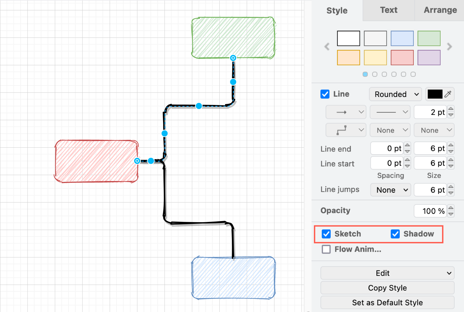
Shadow and Sketch - Add a Shadow to your connector, or make your connector look roughly hand-drawn with Sketch.
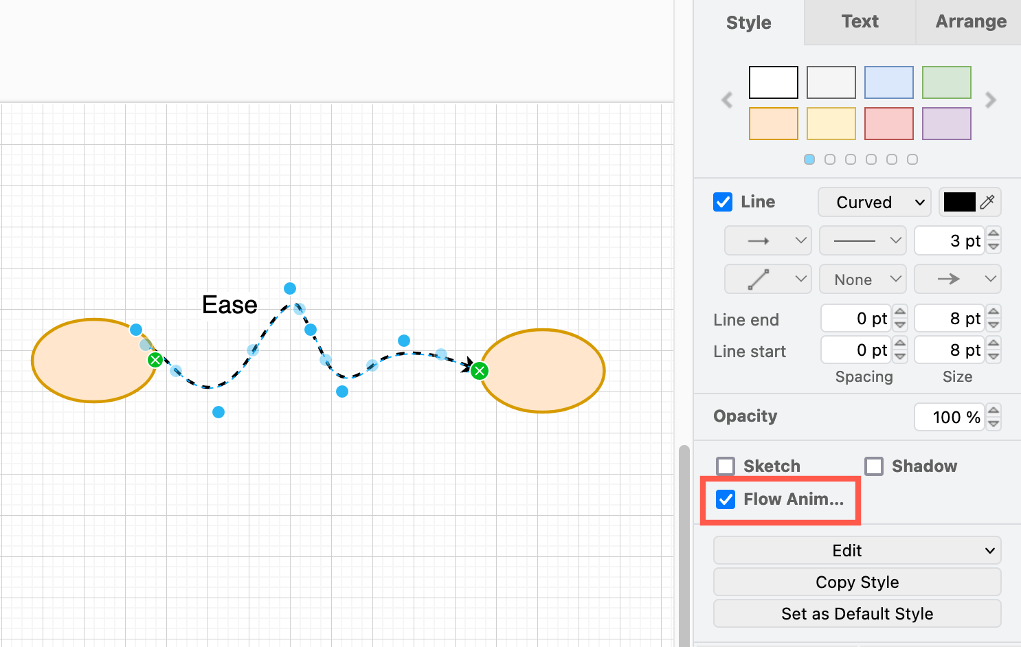
Flow animation - Animate the connector to show the direction of the flow.
Follow terminals - Move the waypoints of the connector along with the connected shapes when you move, resize or arrange them, so the connector keeps its path. Available from version 31.6.2 onwards.
Move waypoints with the connected shapes
Additional connector properties
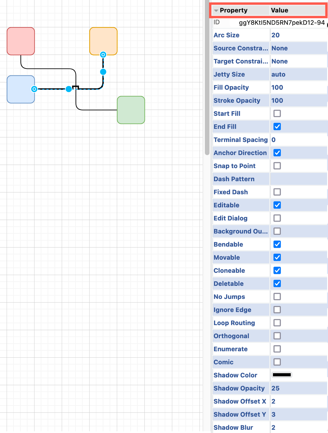
Edit the values in the property list at the bottom of the Style tab to change additional connector style options.
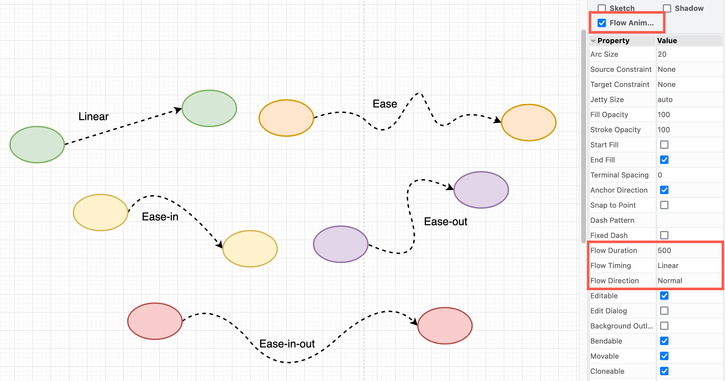
Choose between different connector animation styles and change the speed of the animation via the connector animation Properties.
Set a default connector style
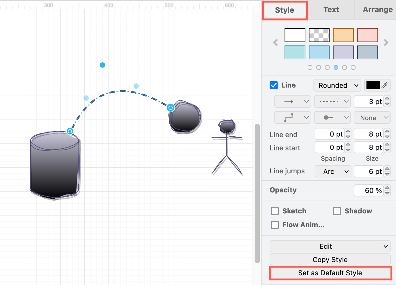
Style a connector on the drawing canvas first, then click Set as Default Style in the Style tab of the format panel.
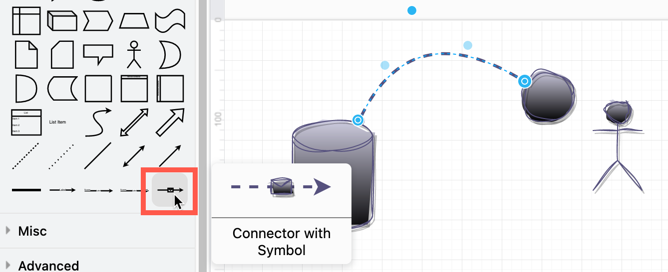
You can see if a default connector style has been set by hovering over a connector in the shape libraries.
Set a default connector style for a specific shape
- Select a connector that is attached to a shape (source).
- In the Style tab of the format panel, click Set as Default for New Connections in the Style tab of the format panel or in the right-click menu.
New connectors that you draw from the source shape of the selected connector will use this style from now on. To remove the default connector style from that shape, select the shape and choose Clear Default for New Connections.
Manually edit a connector's style
Use key=value pairs to define the connector (edge) style in the diagram editor configuration.
- Right click on a connector, then select Edit Style.
- Edit the style definition, then click Apply to save your changes.
