Flow layouts
Select Arrange → Layout → Vertical Flow… / Horizontal Flow… to arrange the diagram's shapes in aligned columns or rows along the direction of flow indicated by the connectors — from top to bottom (Vertical) or left to right (Horizontal),
Shapes are placed so that connectors run with the flow wherever possible and connector crossings are kept to a minimum. Space is reserved between columns/rows for connector labels.
Flowcharts, process diagrams, dependency graphs — any diagram type with an overall direction of flow can use this layout.
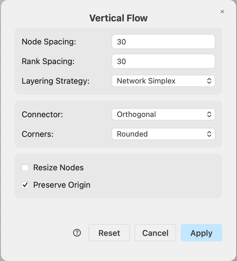
Flow layout options
Node Spacing (default 30) — the minimum distance in pixels between shapes within the same row/column.
Rank Spacing (default 30) — the distance in pixels between one row/column and the next. Increase it to give long connector labels or many parallel connectors more room between rows/columns.
Layering Strategy — how shapes are assigned to rows/columns:
- Network Simplex (default) — picks rows/columns so that the overall connector length is minimized. Usually results in the the most compact and balanced result.
- Longest Path — a simpler strategy that uses the minimum possible number of rows/columns. Fast, but the individual rows/columns can get crowded and connectors longer.
- Coffman-Graham — limits how many shapes share a row/column, trading a longer diagram (more rows/columns) for a narrower one.
Connector — how connectors are routed and drawn after the layout:
- Orthogonal (default) — right-angle routing. Connectors become draw.io orthogonal connectors that follow the computed route and re-route cleanly when you move a shape later. This matches the connectors produced by Mermaid import and AI diagram generation.
- Orthogonal (Strict) — the same right-angle routing, but the computed route is kept bend for bend, so what you see is exactly what the layout calculated. Pick this when faithful routing matters more than easy later editing.
- Polyline — connectors are drawn as straight segments (diagonals allowed) through the computed route, giving a classic graph-drawing look.
Set the corner or bend style of the connectors (sharp / rounded / curved) after applying the layout.
Several other options available in the Flow layout dialog are common to all layouts.
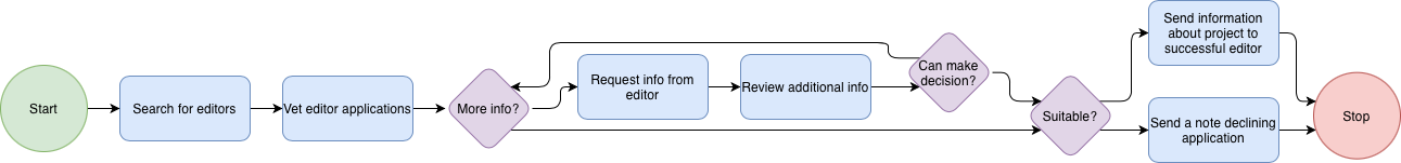
Example flow layout
The horizontal flow layout was applied to a vertical flowchart in this example.